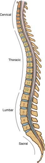
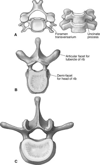
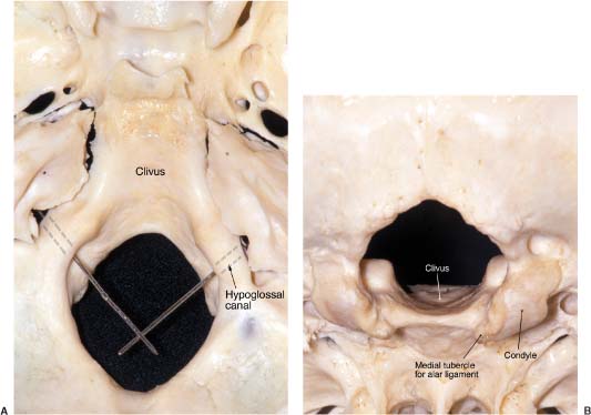
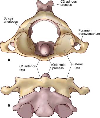
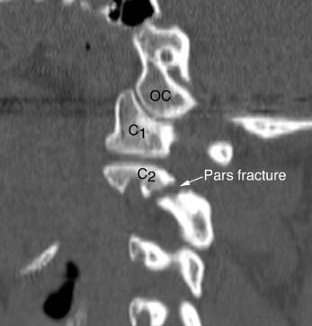
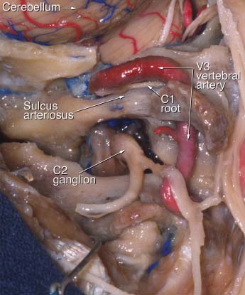
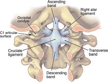
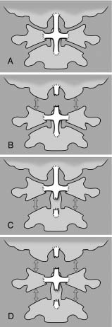
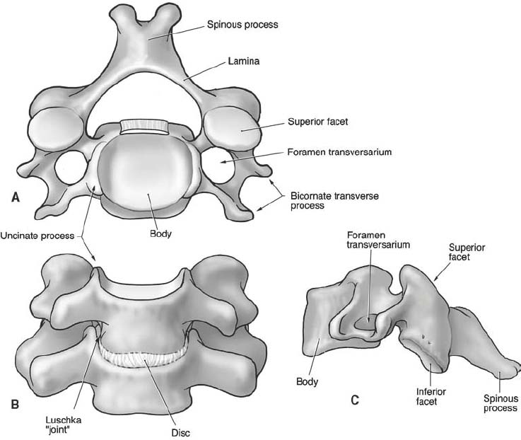
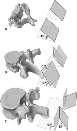
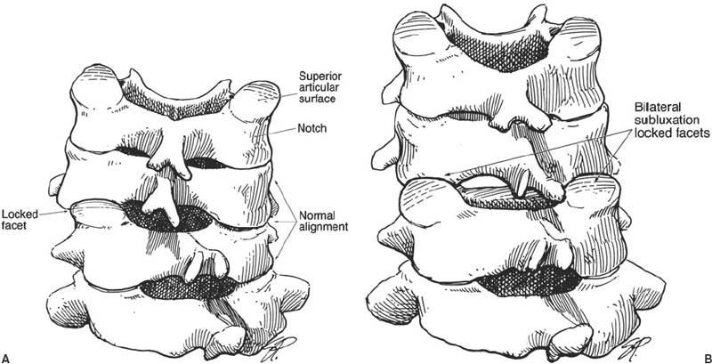
1 This chapter reviews the anatomy of the spinal cord and its osseous relations. The review is intended for spinal surgeons who treat patients with vertebral column or spinal cord lesions. Anatomic relations are described from a functional perspective, and the discussion includes the biomechanical implications of specific anatomic configurations and surgical landmarks for spinal instrumentation. The entire spinal column consists of 33 vertebrae. Seven cervical, 12 thoracic, and five lumbar vertebrae articulate with the fused sacrum (five vertebrae), which articulates with the pelvic rim. Caudal to the sacrum, a small chain of irregular ossicles (usually four) constitutes the coccyx. The vertebral column has four curvatures (Fig. 1-1): cervical, thoracic, lumbar, and sacral. These curves provide flexibility and support the spine. The convexities of the thoracic and sacral segments face posteriorly, whereas the convexities of the cervical and lumbar segments face anteriorly. The cervical lordotic curvature becomes evident when infants can hold their head erect. The thoracic kyphotic curvature results from the slightly wedged shape of the thoracic vertebrae. The lumbar curvature is evident when infants assume an upright posture.1 Variations in vertebral body and disc height are the primary features that form and maintain these curvatures.2 The transition between the mobile lumbar and rigid thoracic curves makes this region particularly susceptible to traumatic injury such as fractures and dislocations. The vertebral column provides a unique structure that protects the spinal cord. The vertebrae have two structural components. The anterior component is composed of a cylindrical structure, the vertebral body, which connects with a posterior arch that encircles and protects the spinal cord.3 The vertebral body is attached to the posterior arch by two horizontal bony structures, the pedicles. On the lateral aspect of the vertebra near the intersection of the pedicle and lamina are (1) the transverse process; (2) the external lateral prominence, which serves as the insertion for the multifidus muscle; and (3) the superior and inferior articular processes, which serve as the insertions for the segmental muscles. The superior articular facet joins a complementary inferior articular process to form a diarthrodial articulation. Posteriorly, the pedicles join with two flat, arched bony structures called laminae that protect the spinal cord posteriorly. Both laminae are connected at the midline and posteriorly by the spinous process. The intervertebral foramen, which forms a canal for radicular vessels and nerve roots, is located between two contiguous pedicles (superior and inferior). The pars interarticularis corresponds to the bony region between superior and inferior articular surfaces. FIGURE 1-1 Sagittal representation of the four physiologic curves of the spine. The cervical and lumbar segments of the spine exhibit a lordotic configuration with an anterior convexity. The thoracic and sacral segments of the spine exhibit a kyphotic configuration with an anterior concavity. Spinal alignment should be neutral in the coronal plane. (With permission from Barrow Neurological Institute.) Each region of the spinal column (Fig. 1-2) has individual characteristics that facilitate their identification. Cervical vertebrae are characterized by small vertebral bodies. Superior bony extensions from the vertebral body, called the uncinate processes, receive the inferior aspect of the superior vertebral body. Cervical vertebrae also have a flat and thin lateral mass with an orifice (foramen transversaria) that serves as a bony canal for the vertebral artery. The thoracic vertebral body is characterized by an articular surface, called the costovertebral joint, for the head of its respective rib. The ribs also articulate with the transverse process at the costotransverse joint. The bodies of the lumbar vertebrae are the largest of the entire spine and have no articular processes for ribs. FIGURE 1-2 (A) The cervical vertebrae are small. On each side the foramen transversarium serves as a bony canal for the vertebral artery. Each cervical vertebral body has superior extensions called uncinate processes that match the respective inferior cervical vertebral body. (B) The thoracic vertebrae are characterized by a true joint on the transverse process that articulates with a respective rib. The shape of the spinal canal is round. (C) The lumbar vertebrae are the largest vertebrae. They lack a prominent articulated transverse processes and have no foramina transversaria. (With permission from Barrow Neurological Institute.) The foramen magnum is composed of a rim formed by the occipital bone, occipital condyles, and clivus. The first two cervical vertebrae, the atlas and the axis, respectively, have special features that distinguish them from the rest of the cervical spine. The occipital bone is divided into a posterior or squamous portion that corresponds to the posterior aspect of the foramen magnum and into a ventral portion, a concave structure around the brainstem that corresponds to the clivus. On both sides of the foramen magnum, the occipital condyle articulates with the atlas (Fig. 1-3). On top of the condyle, the bony hypoglossal canal contains the hypoglossal nerve, artery, and vein. The hypoglossal canal is oriented 45 degrees with respect to midline. Together, both canals create almost a 90-degree angle (Fig. 1-3A). On the medial aspect of the condyle, a bony tubercle serves as the insertion for the alar ligament (Fig. 1-3B).4 FIGURE 1-3 (A) Superior view of the foramen magnum showing its oval shape. Probes inserted in the hypoglossal canals demonstrate the approximate right angle that they form. (B) Posterior and inferior view of the foramen magnum showing the occipital condyles and their medial tubercle where the alar ligaments insert. (With permission from Barrow Neurological Institute.) The first two cervical vertebrae (Fig. 1-4) have special anatomic configurations that are key to understanding their motion. The atlas has no vertebral body per se. Instead, it has a short anterior ring and a posterior curved arch that connects with the lateral mass on both sides. Bilaterally, the vertebral artery pierces the lateral mass through the transverse foramen. Occasionally, the lateral masses can be palpated in the high cervical region posterior to the ascending mandibular ramus. The concave superior articular surface of C1 is oriented rostrally and anteromedially to articulate with the convex occipital condyle, which assumes the same orientation with respect to the midsagittal plane. In effect, the configuration mimics a “ball-and-socket” type of joint. This cup-shaped5 configuration permits a moderate amount of flexion and extension and limits lateral bending and axial rotation. The inferior articular surface of the atlas forms about a 20-degree angle, slanting mediolaterally with respect to the midline, to articulate with the superior articular surface of C2. At the midline the two posterior arches of C1 form a vestigial spinous process (posterior tubercle) to which the deep suboccipital muscles attach. The anterior arch of C1 has an anterior prominence, the anterior tubercle, on which the longus colli muscles attach (Fig. 1-5). The tubercle can be palpated through the posterior aspects of the oral cavity. On the inner surface of the anterior arch of C1 is a synovial-lined articular surface that helps C1 rotate around the odontoid process of the axis. On the inner and medial aspects of the C1 lateral mass, a tubercle serves as the insertion point for the transverse ligament. This ligament constitutes a “seat belt” for the atlas against the odontoid, preventing anterior subluxation of the atlas and permitting normal atlantoaxial rotation to occur. FIGURE 1-4 (A) Superior view of the C1–C2 complex showing the disposition of the odontoid process that allows it to serve as a pivot for axial rotation. (B) Anteroposterior view of the C1–C2 complex showing how C1 (yellow) rests on the shoulders of C2 (magenta). (With permission from Barrow Neurological Institute.) The third portion of the vertebral artery runs in its own groove, the sulcus arteriosus, along the posterior aspect of the superior articular surface of C1, before entering the subarachnoid space through the posterior atlantooccipital membrane. The vertebral artery must be identified during suboccipital approaches. Traditionally, resection of more than 1 cm of the lateral mass of C1 on both sides of the midline is thought to be too risky because the vertebral artery could be compromised. Resection medial to the bony groove on which the vertebral artery courses is safe.6 The axis has a unique configuration. The odontoid (meaning tooth in Greek) process is the most important feature of C2. The odontoid process constitutes the superior projection from the vertebral body, which articulates with C1 anteriorly (anterior arch) and with the transverse ligament posteriorly. The base of the odontoid receives its blood supply from ascending branches of the vertebral artery, and the top is supplied by the apical artery of the odontoid process, a branch of the hypoglossal artery.7 This configuration has clinical implications, especially for odontoid fractures. Once it was thought that fractures involving the neck of the odontoid process would compromise the vascular supply of the dens; however, the vascular supply to the tip was then identified as a vascular arcade and is now recognized as sufficient for healing if the odontoid base is fractured. Each joint anterior and posterior to the odontoid process has its own synovial cavity.4 The pars interarticularis corresponds to the bony region between the superior and inferior articular surfaces and is especially important at the axis. At C2 the pars interarticularis corresponds to the resting site for the entire lever arm from the head when the neck is hyperextended. This region is susceptible to fracture (Fig. 1-6) when the neck and head are forcefully hyperextended. This susceptibility forms the biomechanical basis for a hangman’s fracture. In the lumbar region, the pars interarticularis is key to maintaining the sagittal alignment between two adjacent vertebrae. Pathologic fracture of the par interarticularis constitutes the basis for spondylolisthesis. FIGURE 1-5 Axial representation of the first cervical vertebra. The insertions of the transverse ligament restrain the tip of the odontoid process. Simultaneously, the presence of the articular capsule anteriorly between the odontoid and anterior arch of C1 and posteriorly between the odontoid and anterior arch of C1 permits axial rotation. The sulci arteriosus are wide, horizontally oriented grooves on the posterior arch of C1 that support the third portion of the vertebral artery. (With permission from Barrow Neurological Institute.) FIGURE 1-6 Sagittal CT reconstruction of the upper cervical spine showing the occipital condyle (OC), the lateral mass of C1, and C2 with its pars articularis. A fracture at this location, usually caused by hyperextension of the neck, represents a “hangman’s” fracture. The transverse foramen of C2 is unique. It is located anterolateral to the pedicle8 and is partially covered by the superior facet medially. The transverse foramen consists of an angulated canal with a superior outlet and an inferior inlet.9 This angulation deviates the artery 45 degrees laterally from the midline before it enters the transverse foramen of the atlas.10 The C2 pedicle is the largest of the entire cervical spine.11 It is the bony fragment located medial to the transverse foramen, posterior to the superior articular surface, and anterior to the pars articularis. The diameter of the C2 pedicle is wider at its superior aspect than at its inferior surface because the structure is located medial to the transverse foramen at a particular angle with respect to the vertebral artery.9 The vertebral artery runs through the transverse foramen of C2 (Fig. 1-7). Its position is important to consider when planning the placement of C1–C2 screws. If the diameter of the pedicle is less than 6 mm and the internal diameter of the pars interarticularis is less than 2.1 mm, the vertebral artery might be at risk for injury, and another type of fixation should be considered.12 The position of the vertebral artery needs to be determined before surgery. Computed tomographic angiography (CTA) provides an excellent representation of the bony anatomy and corresponding arterial relations.13 Thin C2 lateral masses, small pedicles, or a high-riding transverse foramen may contraindicate the placement of transarticular screws.14 Placing C2 pedicle screws requires surgical exposure of the medial aspect of the pedicle.15 The entry point is on the superior and medial aspect of the pedicle, and the trajectory is 38 degrees rostrocaudal and 35 degrees lateral to the midsagittal plane.16 The screw is placed under direct visualization. The odontoid process provides the pivot for C1 axial rotation. On the superior articular surface of C2 (shoulders), a plane supports the C1 inferior articular surfaces during axial rotation. This configuration of C1 resting on C2 allows axial rotation, minimal lateral bending, and little flexion or extension. The superior articular surface of C2 is the largest joint surface of the entire cervical spine.17 The odontoid tip has three rough bony prominences that serve as the insertion points of the ligaments that connect the odontoid to the skull base. The odontoid tip is the caudal insertion for the apical ligament, connecting C2 with the anterior rim of the foramen magnum. On both sides of the odontoid tip, bony prominences serve as the insertions for the alar ligaments, connecting C2 to the occipital condyle. FIGURE 1-7 Cadaveric dissection of the right side of the C1–C2 complex showing the third segment of the vertebral artery running from C2 to C1. This horizontal portion of the vertebral artery rests on the sulcus arteriosus adjacent to the C1 nerve root. (With permission from Barrow Neurological Institute.) These ligaments (Fig. 1-8) are extremely important because the biomechanical stability of the craniovertebral junction (CVJ) is based on their integrity. The apical ligament, also known as the middle odontoid ligament or suspensory ligament, attaches the tip of the odontoid to the basion. In one study this ligament was absent in 20% of the specimens, a finding that placed its efficacy in doubt.18 The alar ligament is composed of a pair of ligaments ~1 cm long. It runs between the posterolateral aspect of the odontoid tip and the medial surface of the occipital condyle. The ligament prevents excessive rotation to the contralateral side.19 After one alar ligament is sectioned, the amount of axial rotation increases significantly on both sides.5 Rotation toward the left is limited by the right ligament and vice versa.19 During lateral bending the contralateral ligament, which runs from the dens to the condyle, stretches and limits this movement. Simultaneous coupling of lateral bending and flexion makes the contralateral alar ligament extremely tight and prone to tear. Visualization of the intact alar ligament with magnetic resonance imaging (MRI)20 is of little use because of the artifacts associated with a torn ligament. FIGURE 1-8 Posterior view of the craniovertebral junction (CVJ) in the coronal plane. The posterior arches of C1 and C2, the dura, and the neural contents are removed. The ligaments of the CVJ are exposed. The cruciate ligament is formed by the horizontal transverse ligament and by the vertical ascending and descending bands, which correspond to the segments above and below the transverse ligament, respectively. On each side of the odontoid process, a pair of ligaments, called the alar ligaments, connects the odontoid tip to the occipital condyle. (With permission from Barrow Neurological Institute.) The anatomic configuration of these ligaments is important for understanding why drilling more than 50% of the occipital condyle during a far-lateral approach creates instability at the CVJ. After one ligament is sectioned, exaggerated hyperfixation on the ipsilateral side and increased axial rotation to the contralateral side have been found in a cadaveric model.21 The transverse ligament constitutes the “seat belt” for the atlas relative to the odontoid, thereby preventing anterior C1–C2 subluxation. Experimentally, this ligament is susceptible to rupture when loads between 400 and 1100 N are applied.22 This ligament, which inserts at the inner aspect of the lateral mass of C1, restrains the odontoid against the anterior arch of C1. Its superior extension inserts into the occipital bone, and its caudal extension inserts into the body of the axis. This configuration (caudal, cranial, and transverse) is called the cruciform ligament. The inelastic and stiff transverse ligament is primarily composed of dense collagen with a transitional area between collagen and fibrocartilage, especially at its anterior aspect. This transition is the weakest part of the ligament and is usually the most susceptible to rupture, sometimes with fragments of bone attached to the intact ligament.22 The integrity of the transverse ligament can be assessed with MRI gradient-echo sequences, and the information obtained is important in the decision process about surgical fixation of the C1–C2 complex for traumatic instability.23 When the transverse ligament is torn in a type II odontoid fracture, odontoid screw fixation should not be attempted. This option is reserved for patients with intact ligaments because the stability of the CVJ is based on the integrity of this ligamentous complex. When the superior aspect of the cruciform ligament (Fig. 1-9) and alar ligaments fail, a separation between the occiput and C1 occurs, constituting an occipitoatlantal dislocation with subsequent caudal displacement of the entire spine. When the cruciform ligament fails below the transverse ligament, a vertical C1–C2 subluxation occurs, widening the gap between C1 and C2. The worst case is failure of the cruciform ligament above and below the transverse ligament. C1 is then isolated, and the occipitoatlantal gap and C1–C2 interspace widen. This scenario constitutes an extremely unstable lesion that is often lethal. In our biomechanics laboratory, these mechanisms are under investigation as the underpinnings of different lesions involving the cruciform ligament. The three characteristics unique to the C3–C7 vertebrae are the horizontal foramen in the transverse processes that transmits the vertebral artery, the small size of the vertebral bodies, and the presence of uncinate processes (Fig. 1-10). FIGURE 1-9 Diagrammatic representations of the ligaments involved in the stability of the CVJ. (A) Normal intact ligaments. (B) The superior portion of the cruciform ligament or ascending band is disrupted, widening the gap between C1 and the occipital condyles as is typical of occipitoatlantal dislocation. (C) The lower part of the cruciform ligament is torn, causing vertical distraction between C1 and C2. The ascending band and transverse ligament are intact. (D) Combined lesion in which the transverse ligament is completely separated from the ascending and descending bands. (With permission from J Neurosurg Spine 3:267–272, 2004.) The posterolateral edge of the superior aspect of each small vertebral body turns upward sharply and matches the beveled inferior surface of the rostral vertebral body. This uncinate process is located at the posterolateral margin of the intervertebral space.1 At birth the uncinate process is just barely evident, but it continues to grow in height.24 The uncinate process, which also is called the Luschka joint, constitutes a joint-like articulation; however, Luschka joints are not true joints because they contain no synovial fluid.25 The uncinate process increases the articular surface. Panjabi et al11 measured the articular surface of the cervical spine and found two times more area at the superior articular surface (superior aspect of the vertebral body) than at the inferior aspect. The widths of the cervical vertebral bodies increase progressively from C3 to C7,26 increasing the size of the interspace. This increase is important to recognize during anterior cervical decompression. The cervical disc space has a special configuration. The inferior vertebral end plate is usually concave. The height of the disc at its midaspect is greater than elsewhere.26 This configuration makes the anterior end plate tilt slightly superiorly when the disc is removed. The depth of the cervical vertebral bodies varies. At C3 it averages 16 mm, whereas at C7 it averages 20 mm.26 This progressive increase is important to remember when a screw length is selected for anterior cervical plating. The depth at the inferior end plate is greater than the depth at the superior aspect of the next caudal vertebra. This feature is important when the implantation of bicortical screws is considered. Recognizing the presence of the sympathetic chain over the longus colli muscle is key to preventing iatrogenic Horner’s syndrome. The longus colli muscles extend from the anterior tubercle of the atlas to the anterior vertebral body of T3 on both sides. Both muscles form a triangle with its vertex pointed rostrally and a wide caudal base. The sympathetic chain runs over this muscle and is prone to injury during an anterior approach to the cervical spine. To prevent Horner’s syndrome, manipulation or dissection of the longus colli lateral to its medial insertion must be minimized.27 Another source of Horner’s syndrome is injury to the stellate ganglion located between the lateral border of the longus colli muscle and the base of the C7 transverse process.27 Dissection, however, must be quite lateral to compromise the sympathetic fibers at this caudal level. From C3 to C6 the foramen transversarium is progressively displaced posteriorly, making the vertebral artery be closer to the neural foramen at more rostral levels.28 Bilaterally, each cervical vertebra has a small bicornuate transverse process. The anterior aspect constitutes fused costal elements. The posterior aspect serves as an insertion point for cervical muscles. In the cervical spine, the facets are predominantly oriented coronally. Panjabi et al17 proposed a model that showed the orientation of the facet as a card (Fig. 1-11 ). The cervical facets create a small angle with respect to the coronal plane and a large angle with respect to the axial plane (60 to 90 degrees). Both C6 and C7 (especially) are transitional vertebrae. The surface of their facets is oriented coronally, similar to the facets of the thoracic region.29 The superior and inferior articular processes have a complementary oblique configuration relative to the sagittal plane. The inferior articular process is posterior to the superior articular process of the adjacent inferior vertebrae. FIGURE 1-10 Three different views of a cervical vertebral. (A) In the superior view, the foramen transversarium can be seen on each side. This foramen hosts the vertebral artery. (B) Frontal view showing the uncinate process on each side of the vertebral body. The well-known “Luschka joints” do not represent true joints because they lack a true articular surface; they are called joints because they are so well opposed to each other. (C) Lateral view showing the coronal orientation of the facets and the funnel for the cervical roots. (With permission from Barrow Neurological Institute.) Traumatic hyperflexion of the cervical spine associated with a rotational component is the main mechanism underlying a misalignment between the superior aspect of the caudal vertebrae and the inferior articular aspect of the rostral vertebrae called a locked facet (Fig. 1-12). If a locked facet does not reduce with cephalic traction, it is necessary to reproduce the mechanism of injury. Using manual traction, hyperflexion and rotation to the opposite side will reaccommodate the facets in their anatomic position. The cervical laminae are shorter and thinner than the thoracic laminae.30 Their superior aspect is narrow, and their base is wide. They join at the midline in a bifid spinous process that serves as an insertion point for the semispinalis muscles. Cervical pedicles are markedly smaller than the pedicles of other segments. From C3 to C7 the mean diameter of cervical pedicles ranges from 6.0 to 6.5 mm.31 The internal diameter of the pedicle ranges between 2.7 and 3.1 mm.32 Cervical transpedicular screws are therefore extremely challenging to place to avoid injuring the vertebral artery or nerve root or to avoid entering the spinal canal with the screw.15,33 There is a small gap between the lower part of the pedicle and the superior aspect of the nerve root.31 The inferior aspect of the nerve root directly contacts the superior aspect of the respective pedicle. The medial aspect of the pedicle directly contacts the thecal sac on its lateral surface.34 The relationship between the pedicle and nerve root is an important consideration when placing cervical pedicle screws or performing discectomies from a posterior cervical approach. The angle of the cervical pedicle between the axis of the pedicle and the midsagittal plane ranges from 38 to 48 degrees.32 This angle is a key landmark when cervical transpedicular screws are placed. The cortex is thinner on the lateral aspect of the pedicle than on the medial side, making the vertebral artery vulnerable to trauma when screws violate the margins of the lateral pedicle.33 Considering the variability in the shape and dimension of the pedicles, preoperative computed tomography (CT) and intraoperative computed-assisted frameless stereotactic navigation are valuable when cervical pedicle screw fixation is planned.33 A reliable surgical landmark for finding the pedicle is to identify the vertebral notch. The notch represents the most medial point on the ridge of the pars interarticularis and the middle third of the inferior articular process. The intersection between these two points marks the entry point for pedicle screws in the subaxial cervical spine (C3–C6). For C7 the intersection between the previous two points and the base of the transverse process determines the entry point for the pedicle.15 FIGURE 1-11 Representation of (A) cervical, (B) thoracic, and (C) lumbar vertebrae showing the differences in the orientation of the facets. (A) The facets of the cervical vertebral are characteristically oriented ~45 degrees with respect to the coronal plane. (B) Thoracic vertebral are oriented sagittally and coronally simultaneously. (C) The lumbar vertebra creates almost a 45-degree angle with respect to the sagittal plane and at the same time a vertical positioning. (With permission from Barrow Neurological Institute.) Morphologically and biomechanically, the seventh cervical vertebra is a transitional vertebra. The mechanical loads placed on the cervical region are less than the loads supported by the thoracic spine. The long spinous process of C7 (vertebral prominence) is easy to distinguish by palpation because it is the longest process of the cervical spine. The C7 lateral masses are large and thin.35,36 Their transverse foramina are variable and unequal, and the vertebral artery seldom passes though them.28 The largest cross-sectional area of the cervical pedicles is at the cervicothoracic junction.37 External landmarks are important for identifying the pedicle of C7 to prevent neurovascular injuries to anterior structures. Xu et al38 studied 56 bilaterally dissected C7 specimens. After the lateral mass of C7 was exposed, the entry point for the pedicle was 2 mm medial to the lateral edge of the facet and 0 to 2 mm inferior to the midplane through the transverse process at C7. The angle from the plane of the lateral mass was 107 degrees, and the angle from the midsagittal plane was 76 degrees. These two reference landmarks were constant in all specimens. It is important to recognize that contiguous structures are different at different levels of the cervical spine. Muscular structures, nerve roots, and the brachial plexus are located anterolateral to the vertebral bodies from C4 to C7, whereas the pleural cavity appears around T1. The pharynx and esophagus have a fairly constant anterior relation to the vertebral bodies in the cervical and thoracic spine. In the cervical spine, the nerve roots, ganglia, and vertebral artery are anterior to the lateral mass. The nerve root and vertebral artery are positioned lateral to the cervical pedicles throughout the entire cervical spine. In the thoracic spine the rib heads are positioned just lateral to the pedicles, and the major vascular structures are not too close to the pedicles (i.e., aorta, azygos veins).39 This configuration makes the placement of pedicular screws relatively safe compared to their placement in the cervical spine. The oblique orientation of the lateral masses between C3 and C7 requires orienting lateral mass screws superiorly to prevent injury to the nerve root and vertebral body. A perpendicularly placed screw may be more dangerous than an angulated one.29 We prefer to drill a small pilot hole beginning 1 or 2 mm medial to the midpoint of the inferior articular surface, angled 15 degrees cephalad and 20 to 30 degrees laterally. This trajectory protects the nerve root and vertebral artery.40 The intervertebral foramen is limited superiorly and inferiorly by their respective pedicles; posteriorly by the facet; and anteriorly by the posterolateral aspect of the uncovertebral joint, the intervertebral disc, and the inferior aspect of the superior vertebral body. The foramen, which can be as long as 2 cm, has a unique funnel shape with a narrow proximal opening and a wider distal end.41 The nerve courses through the foramen in a groove that extends medially from the pedicle to the lateral end of the transverse process. Laterally, the nerve root is positioned posterior to the vertebral artery (V2 segment) and anterior to the superior articular facet.42
Anatomy of the Spine and Spinal Cord
 Anatomy of the Spinal Column
Craniovertebral Junction

Subaxial Cervical Vertebrae (C3–C7)
Related posts:
 Brachytherapy for Malignant Spinal Tumors
Sacral Tumors: Primary and Metastatic
Primary Vertebral Column Tumors
Thoracotomy and Thoracoabdominal Transdiaphragmatic Approaches to the Thoracic and Lumbar Spine
Pedicle Screw Fixation of the Thoracic and Lumbar Spine
Thoracoscopic Resection of Intrathoracic Paraspinal Neurogenic Tumors
Brachytherapy for Malignant Spinal Tumors
Sacral Tumors: Primary and Metastatic
Primary Vertebral Column Tumors
Thoracotomy and Thoracoabdominal Transdiaphragmatic Approaches to the Thoracic and Lumbar Spine
Pedicle Screw Fixation of the Thoracic and Lumbar Spine
Thoracoscopic Resection of Intrathoracic Paraspinal Neurogenic Tumors
Stay updated, free articles. Join our Telegram channel

Full access? Get Clinical Tree


