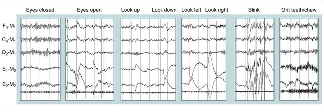
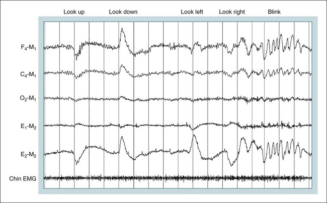
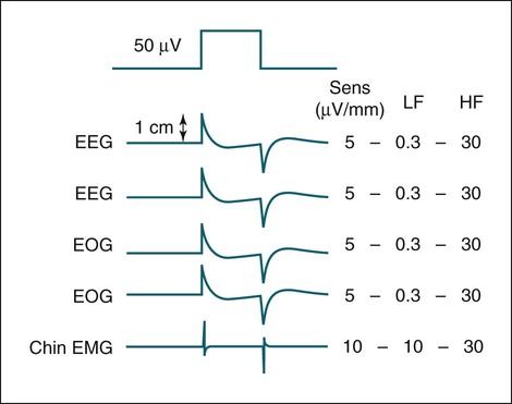
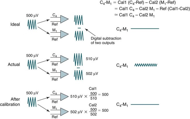
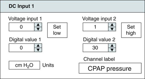
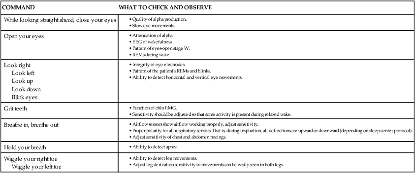
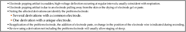
• Recording a technically adequate biocalibration is an important part of every sleep study. Careful attention to the recorded biocalibration by the scorer or physician reviewing the study is essential for identifying the individual’s pattern of eyes-open and eyes-closed wakefulness as well as the appearance of eye movements. The biocalibration may help the scorer differentiate stage W with REMs from stage R when the chin EMG is at a low level in both sleep stages. • A 60-Hz artifact is recognized as a ropelike pattern. If there is a large increase in the signal amplitude when the 60-Hz notch filter is turned off (especially with a 100 Hz high filter setting), this implies significant 60-Hz contamination of the signal. High electrode impedance is a common cause of 60-Hz artifact. • The ideal electrode impedance is less than 5 KΩ (acceptable <10 KΩ). • ECG artifact can be minimized by correct mastoid electrode placement. During review, ECG artifact can be minimized by using an average of the mastoids (e.g., F4-Avg) or linking the electrodes. • Sweat artifact (sway) can be minimized by cooling the patient down or using different derivations if movement of one of the mastoid electrodes is causing the problem. • Electrode popping is a serious artifact and requires replacement or fixing the faulty electrode (or preventing movement of the electrode with each breath) during recording. • A large amount of sleep spindle activity may be a clue that the patient is taking a BZRA. • Eye movements may persist in stage N2 sleep in patients taking SSRIs. • Prominent alpha activity can be seen “riding” on top of SWA in alpha-delta sleep. Increasing the viewing window to 10 seconds and counting waveforms can help confirm that prominent alpha activity is present. Calibration was especially critical during paper recording to document the individual amplifier sensitivity, polarity, and filter settings because these could not be changed once data were recorded. In the digital era, electroencephalographic (EEG), electro-oculographic (EOG), and electromyographic (EMG) data are acquired at a default gain and with a wide bandpass (e.g., 0.03 and 100 Hz, respectively). The desired channel sensitivity and filter settings for the display of individual channels (traces) can be changed during acquisition and review. In the paper era (Fig. 4–1), calibration was usually performed by sending a square wave voltage pulse (typically 50 µV). The sensitivity control was adjusted until a 50-µV signal produced a 10-mm pen deflection (others used 75 µV for 10 mm). Digital systems today often send a sine wave signal of standard frequency (5 or 10 Hz) and peak-to-peak voltage (100–500 µV) to the amplifier to document digital system accuracy (Fig. 4–2). Whereas the analog amplifier gain used in digital systems usually cannot be adjusted except by the manufacturer, the computer program can change calibration factors to more accurately display the recorded data. If large adjustments are necessary, the program will often provide notification that amplifier service is needed. The output of each individual AC amplifier can be scaled by calibration factors so that they provide exactly equivalent outputs from the calibration signal. In Figure 4–2, a 500-µV calibration signal results in slightly different outputs from the amplifiers processing the C4-Ref and M1-Ref signals. Calibration factors are selected to scale the outputs to the input standard. After scaling, the digital values used for display match the input calibration voltage and, even more important, the two amplifiers deliver the same exact output from the calibration signal. This improves common mode rejection during referential recording. That is, the same signal applied to both amplifiers should result in zero output when the derivation using them is displayed (digital subtraction). Calibration of DC signals (Fig. 4–3) is usually performed using a two-point calibration method. This is performed by sending a lower and higher signal (usually 0 and 1 V or –1 and 1 V) and specifying the parameter values corresponding to the two voltages. For example, a positive airway pressure device and analog module outputs 0 V for 0 cm H2O pressure and 1 V for 30 cm H2O. The device would be directed to send 0 V to the digital system and 0 cm H2O pressure is specified using the polysomnography (PSG) software. Then 1 V is sent and 30 cm H2O is specified. There is usually an option to type in the expected voltage or to actually measure the voltage sent by the device at each of the two calibration points. For example, when the low calibration voltage is sent the set low button is pushed. This action displays the actual voltage in the voltage input 1 window (Fig. 4-3) and sends value to the computer for computation of the calibration factors. A similar procedure is performed when the high calibration voltage is sent. The computer then determines and stores the calibration factors. Biocalibration (Table 4–1 and Fig. 4–4) is an important part of every PSG recording, but the value of the procedure is often unrecognized. During the biocalibration, signals are recorded while the patient performs maneuvers that verify that the monitoring equipment, electrodes, and sensors are working properly. The impedance of all EEG, EOG, and EMG electrodes should be checked. For the reviewer, noting the patient’s EEG, EOG, and EMG pattern of eyes-open and eyes-closed stage W can help with recognition of this sleep stage during the recording and during scoring of sleep. It is especially important to know whether the person being recorded generates alpha activity with eye closure because this affects the scoring criteria for stage W and stage N1 (see Chapter 3). TABLE 4–1 EEG = electroencephalogram; EMG = electromyogram; REMs = rapid eye movements. Figure 4–5 shows a portion of the biocalibration procedure in a patient with a prior left eye enucleation. Hopefully, technologist’s notes and patient history would have alerted the reviewing physician to this situation. However, looking at the biocalibrations would also alert the physician that stage R sleep would have an unusual appearance. Artifacts in the EEG, EOG, and EMG derivations due to inadequate electrode application or the effects of patient movement and the environment are common in polysomnography.1–4 It is essential that they be recognized during recording to allow for intervention by the sleep technologist. Postrecording maneuvers to minimize the effects of some artifacts on sleep staging are often possible. Electrode popping is a common and severe artifact that makes the staging of sleep very difficult (Table 4–2). It is characterized by sudden, high-amplitude deflection (often with channel blocking) secondary to an electrode pulling away from the skin (sudden loss of signal). The popping often tends to be regular and corresponds to body movement during breathing. Electrode popping may also be caused by the patient lying on one mastoid electrode or pulling on the wire connecting the electrode with the electrode box during respiration. For example, if the wire runs under the patient’s body or through chest or abdominal bands, patient movement or respiration can pull on the electrode wire. Popping also can occur if the electrode gel dries out during the night. At the time of recording, adding electrode gel or reapplication of the problem electrode may eliminate the problem. Postrecording, the artifact can frequently be handled by switching to an alternative derivation that does not use the problem electrode. For example, if O2 is the problem, the exploring occipital electrode is switched to O1. This is one reason that redundant electrodes are routinely placed. TABLE 4–2 In Figure 4–6, regular high-voltage deflections are noted in all derivations containing M1. Therefore, the problem is most likely in electrode M1. Video monitoring confirmed that the patient was sleeping on the left side. After changing the reference electrode to M2 (using derivations F3-M2, C3-M2, O1-M2, E1-M2, and E2-M2), the problem was eliminated. Displaying F4-M2, C4-M2, O2-M2 would also eliminate the artifact. However, using an exploring electrode opposite the reference is preferable because this produces a larger voltage signal. In fact, F3-M2, C3-M2, and O1-M2 are the alternate derivations recommended by the American Academy of Sleep Medicine (AASM) scoring manual. If an electrode in the standard derivation fails, use of corresponding electrode in the alternate derivation set for sleep monitoring is recommended (see Chapter 1).
Biocalibration, Artifacts, and Common Variants of Sleep
Calibrations and Biocalibrations
Calibrations
Biocalibrations
COMMAND
WHAT TO CHECK AND OBSERVE
While looking straight ahead, close your eyes
Open your eyes
Look right
Look left
Look up
Look down
Blink eyes
Grit teeth
Breathe in, breathe out
Hold your breath
Wiggle your right toe
Wiggle your left toe
Artifacts
Electrode Popping
![]()
Stay updated, free articles. Join our Telegram channel

Full access? Get Clinical Tree


Biocalibration, Artifacts, and Common Variants of Sleep