29 C1-C2 Techniques
I. Key Points
– Fixation choices are (1) C1 lateral mass screws in combination with C2 pars screws, pedicle screws, or translaminar screws; (2) C1-C2 transarticular screw (Magerl’s technique); or (3) wiring techniques.
– Posterior C1-C2 fusion techniques are technically demanding and caution should be used to avoid vascular (vertebral and carotid arteries) injury during screw placement.
– Preoperative computed tomography (CT) scan (with or without CT angiography) is helpful to assess the position of the foramen transversarium of C1 and C2.
II. Indications
– Most C1-C2 ligamentous instabilities (>3 mm atlantodental interval [ADI] on flexion-extension x-rays in an adult without rheumatoid arthritis)
– Traumatic fractures are among the most frequent indications for posterior C1-C2 fixation.
– Certain subsets of type 2 and type 3 odontoid fractures are amenable to posterior C1-C2 fixation.
• Type 2 odontoid fracture associated with
 Fracture of the atlantoaxial joint
 Anterior-inferior oblique fracture in the coronal plane
 Oblique fracture in the frontal plane
 Jefferson fracture
 Ruptured transverse ligament
 Old, unhealed type 2 odontoid fracture
• Type 3 odontoid fracture associated with
 Fracture of the atlantoaxial joint
 Jefferson fracture
 Chronic unhealed odontoid fracture after immobilization; rotatory subluxation of C1-C2
– Congenital malformations of C2 (e.g., os odontoideum and odontoid agenesis with C1-C2 dynamic instability)
– Inflammatory diseases (e.g., rheumatoid arthritis with >7 mm ADI)
– Degenerative diseases (with instability and abnormal ADI)
– Infections (with instability and abnormal ADI)
– Neoplasms (with instability and abnormal ADI)
III. Techniques
The procedure is technically demanding, and an exact three-dimensional (3D) understanding of the anatomy of the region and of the vertebral artery is mandatory.
The patient is positioned prone with head fixed by a Mayfield head holder (Schaerer Mayfield, Randolph, MA). The neck should be in the neutral position and the head kept in the military chin tuck position. A midline posterior neck incision is then made from the suboccipital area to the spinous process of C3, allowing exposure of C2-C3 facet joints and the posterior C1 arch.
C1 Lateral Mass Screw with C2 Pars, Pedicle, or Translaminar Screws1,2
• Control of hemorrhage from the venous plexus between C1 and C2 must be achieved by bipolar coagulation or hemostatic agents. It is not necessary to expose the vertebral artery on the superior aspect of the C1 arch (sulcus arteriosus). Usually the C2 nerve root is mobilized caudally for exposure of the C1 lateral mass inferior to the C1 arch. The medial border of the C1 lateral mass is palpated. A pilot hole can be made with a 3 mm drill bit at the center of C1 lateral mass. The screw trajectory is 10 degrees medial angulation in the axial plane. On lateral fluoroscopic imaging the drill is aimed toward the anterior tubercle of C1. Stop the drill at the “back side” of the anterior C1 tubercle to prevent plunging the bit into the retropharynx. After tapping of the hole, the C1 lateral mass screw is placed (usually 34 to 36 mm in length).
– C2 pars screws (Fig. 29.1)5,6
• The C2 pars is defined as the portion of C2 vertebra connecting the superior and inferior articular surfaces. A C2 pars screw is placed in a trajectory similar to that of a C1-C2 transarticular screw, except that it is shorter. Its entry point is about 3 mm rostral and 3 mm lateral to the inferior medial aspect of the inferior articular surface of C2. The screw should follow a steep trajectory, 45 to 60 degrees, with 10 to 15 degrees of medial angulation. Typical screw length is 16 mm, but the screw must stop short of the transverse foramen (check with preoperative CT scan). The risk of vertebral artery injury for C2 pars screws is lower than that for C1-C2 transarticular screws.
– C2 pedicle screws
• The C2 pedicle is the portion of the C2 vertebra that connects its posterior elements to the vertebral body. The entry point of the C2 pedicle screw is in the pars of C2, lateral to the superior margin of the C2 lamina. This is usually 2 mm lateral and 2 mm superior to the C2 pars screw entry point described above. The pedicle screw requires a medial angulation of 15 to 25 degrees with 20 degrees upward trajectory. For those with very narrow C2 pedicles, risk of breach into the neural canal or transverse foramen is high (check with preoperative CT scans).
– C2 translaminar screws
• Translaminar screws serve as a salvage technique for C2 pars screws or pedicle screws in cases of the anomalous high-riding vertebral artery or very thin pedicle. The entry point is at the junction of the spinous process and lamina. The trajectory has to meet the slope of the lamina while aiming mildly dorsally to avoid canal breach. If bilateral translaminar screws are used, offset the entry points craniocaudal to keep the two screw paths from intersecting.
• Using polyaxial screws, the C1 lateral mass screws can be easily connected with either of the three kinds of C2 screws described above.
– C1-C2 transarticular screws
• The advantage of the C1-C2 transarticular screw technique is the complete obliteration of the rotational motion of the atlantoaxial joint. The drawbacks of this procedure are the need for anatomical reduction of C1-C2 and the potential for vertebral artery injury. If placement of the first screw likely caused vertebral artery injury, then screw insertion into the contra-lateral side should not be attempted, because bilateral vertebral artery laceration could result in brain stem infarction and death. The preoperative CT scan must be carefully examined to exclude a high-riding vertebral artery or destruction of bone at the site of intended screw placement.
• The screw entry point is approximately 3 to 4 mm rostral and 3 to 4 mm lateral to the inferior medial portion of the C2-C3 facet joint. The K-wire trajectory is typically 15 degrees medial with the superior angle visualized by fluoroscopy aiming at the C1 anterior tubercle (often 60 degrees). While the K-wire is drilling, subtle changes in resistance may be perceived as the K-wire traverses the four cortical surfaces along the path into the C1 lateral mass: (1) the posterior C2 entry point, (2) the superior articular surface of C2, (3) the inferior articular surface of C1, and (4) the anterior cortex of the C1 ring. After the K-wire is placed, a cannulated drill bit, tap, and screw can be placed. Typical screw length is 36 to 46 mm.
– Wiring techniques
• Posterior wiring techniques require an intact posterior arch in each of C1 and C2. Therefore, in cases of Jefferson fracture or hangman’s fracture the K-wire is of no use. Double-braided titanium cables are preferred (over steel wires) because they are more flexible and have less chance of causing cord or dural injury during the sublaminar passage. Several techniques of sublaminar wiring and bone graft placement have been reported, including the Sonntag wiring, the Brooks wiring, and the Gallie wiring.
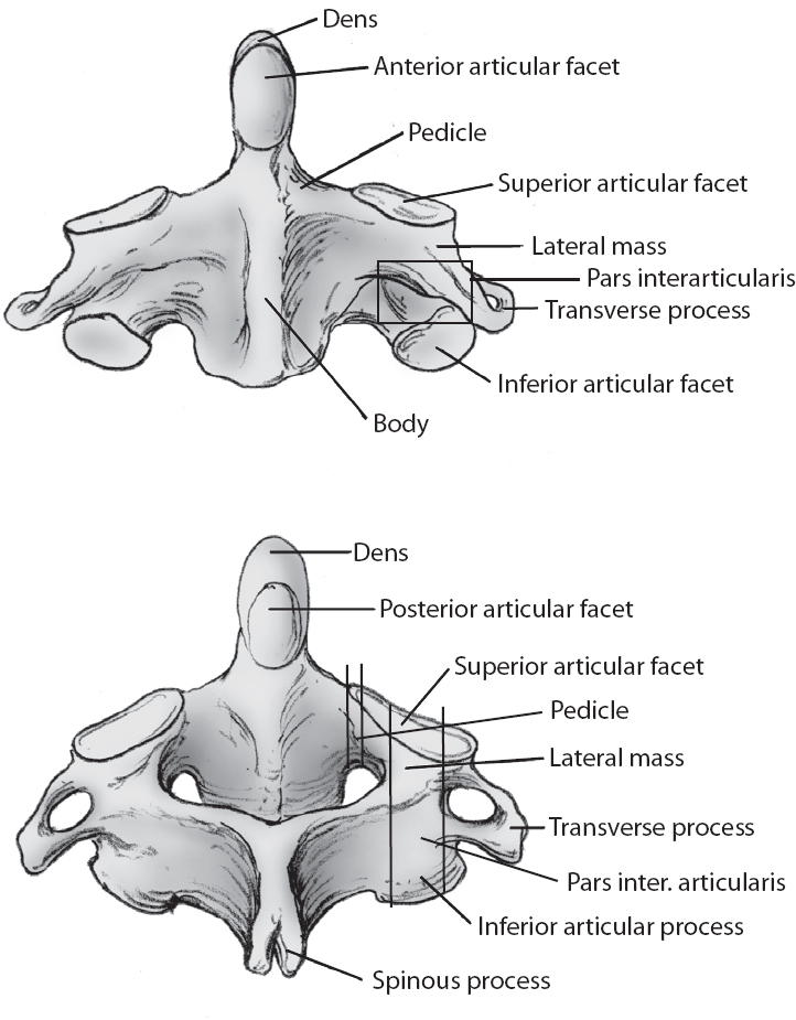
Fig. 29.1 Anatomy of the axis (C2). (From Fessler/Sekhar, Atlas of Surgical Techniques, Thieme, pg. 138, Fig. 16.3A,B. Reprinted with permission.)
IV. Complications
– Vertebral artery laceration (unilateral vertebral artery occlusion could be asymptomatic, but bilateral vertebral artery injury could result in a large posterior circulation infarction and death). If there is a unilateral vertebral artery injury, consider placing the screw into the bone to tampanade the bleeding. Consider not placing the contralateral screw. Consider taking the patient for a postoperative angiogram to ensure there is no artery dissection.
V. Postoperative Care
– No need for external orthosis if rigid screw fixation is achieved.
VI. Outcomes
– Transarticular screws together with the Sonntag wiring technique and bone graft essentially create a three-point fixation that completely obliterates the rotational and flexion-extension motion of the C1-C2 joint. Apfelbaum reports that fusion was achieved in 99% of 198 patients undergoing transarticular screw fixation. However, Apfelbaum also reported a 16.7% complication rate, including 5 patients with vertebral artery injuries, one of which was bilateral and fatal.3
– C1 lateral mass screws connected to C2 pars/pedicle, or translaminar screws, provide biomechanical strength and actually facilitate anatomic reduction with a fusion rate higher than 95%.4
– Biomechanical analysis in cadaveric specimens showed crossed translaminar fixation to be superior to pars screws in strength.
VII. Surgical Pearls
– Preoperative planning is crucial. The CT scan must be evaluated to rule out an anomalous vertebral artery path and to assess the bony anatomy.
– A thorough understanding of the 3D anatomy of the axis and atlas is mandatory.
– Be aware of the robust venous plexuses around the C1-C2 region and use a hemostatic agent to diminish bleeding in this area.
Common Clinical Questions
1. Where is the entry point for the C2 pars screw?
2. Where is the entry point for the C1-C2 transarticular screw?
3. Should you place a contralateral C2 pars screw if you have an ipsilateral vertebral artery laceration during insertion of the first C2 pars/pedicle or transarticular screw?
Related posts:


Stay updated, free articles. Join our Telegram channel

Full access? Get Clinical Tree


