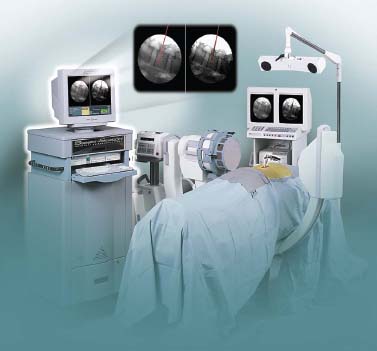
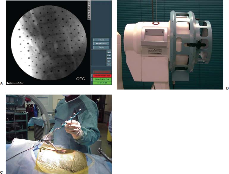
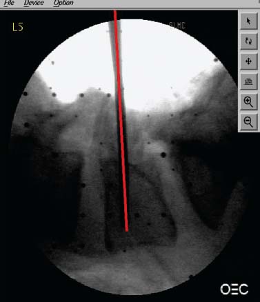
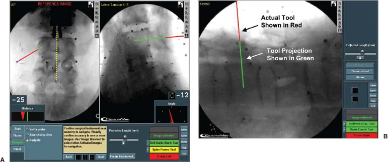
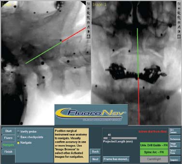
Fluoroscopy is an imaging technique that is familiar to spinal surgeons. It is routinely employed to improve intraoperative visualization of bony anatomy. By replacing direct visualization with radiographic visualization, it has enabled a reduction in surgical exposure, duration, and blood loss. Its use has facilitated a variety of complex spinal procedures, including pedicle screw insertion, interbody cage placement, odontoid screw insertion, and atlantoaxial transarticular screw fixation. Despite its widespread acceptance and utility, however, fluoroscopy has disadvantages. The most notable is occupational radiation exposure, particularly to the surgeon’s hands.1–3 Data have suggested that spinal surgeons, in particular, are at significant risk for fluoroscopy-related radiation exposure.4 Furthermore, the C-arm can be cumbersome to maneuver around a sterile operative field. Because only a single projection can be visualized at one time (without a second fluoroscope), it is necessary to reposition the C-arm during procedures that require multiple planes of visualization. This process is often tedious, time consuming, and frustrating. A desire to improve intraoperative visualization led to the development of image-guided surgery systems for spinal surgery. The first such systems were CT based and were an extension of systems used for cranial neurosurgery. Further development of image-guided technology has resulted in a second class of systems that differ in terms of the type of imaging that is used to provide the image guidance. These systems are based on fluoroscopy itself. By combining current C-arm fluoroscopy with computer-aided surgical technology, many advantages of fluoroscopy can be enhanced and its disadvantages minimized or eliminated. A fluoroscopy-based system employs commonly available C-arms augmented with accessories that allow accurate measurement of the relationship between the C-arm and the patient. The system takes patient and C-arm position data for a given projection and relates the data to the fluoroscopic image from that projection. After calibrating the system with positional and fluoroscopic data from one or more projections, the computer generates a mathematical model of the fluoroscopic image that enables the superimposition of tracked surgical instruments onto the saved fluoroscopic images. Thus, the real-time position of these instruments is displayed as it relates to one or more previously acquired fluoroscopic images, even in multiple planes, simultaneously. We term this process virtual fluoroscopy (Fig. 33–1). The advantages of virtual fluoroscopy are that no special preoperative study is required, intraoperative patient registration is automated, and the images may be updated as necessary in the operating room. Fluoroscopy-based systems are available that are either integrated with conventional image-guided surgery systems (FluoroNav Virtual Fluoroscopy System and StealthStation, Medtronic Surgical Navigation Systems, Louisville, CO) or exist as stand-alone devices (StealthStation Ion Fluoroscopic Navigation System, Medtronic Surgical Navigation Systems, Broomfield, CO). Materials and Methods A typical virtual fluoroscopy system consists of an image-guidance computer system, a commercially available fluoroscopic C-arm, a calibration device that attaches to the C-arm, and specially modified surgical instruments that are capable of being tracked by the image-guidance system. The system may be operated by the surgeon through a sterile interface, or it may be operated by an assistant. The operation of a virtual fluoroscopy system may be divided into four basic steps (Fig. 33–2): FIGURE 33–1 Virtual fluoroscopy. Operating room setup integrating fluoroscopic images with previously acquired images. Step 1: fluoroscopic image acquisition Step 2: C-arm and patient position measurement Step 3: merging of the fluoroscopic images with their unique C-arm and patient positions to create a mathematical model (mapping) of the image formation process Step 4: measurement of the position of surgical instruments in the operative field so that their likeness may be superimposed on the virtual fluoroscopic images System Accuracy The accuracy of various virtual fluoroscopy systems has been tested experimentally. Foley et al5 performed a cadaver study comparing live and virtual fluoroscopic images in which a tracked probe was inserted into pedicles from L1 to S1. Differences in positioning the probe tip and probe trajectory angle were measured for the live and virtual images. The mean error in probe tip localization was 0.97 ± 0.40 mm (99% confidence interval = 2.2 mm, maximum probe tip error = 3 mm). The mean trajectory angle difference between the virtual and actual probe images was 2.7 degrees ± 0.6 degrees (99% confidence interval = 4.6 degrees, maximum trajectory angle difference = 5 degrees). (Fig. 33–3) FIGURE 33–2 Fluoroscopic image-guided spine surgery. (A) Fluoroscopic images are acquired and calibrated (anteroposterior, lateral, oblique, etc.). (B) Calibration target with affixed light-emitting diodes attached to an OEC Model 9600 C-arm fluoroscope. (C) The reference arc is applied to the anatomy; any rigid surgical instrument can now be tracked simultaneously on all views. Operative Techniques Open Pedicle Screw Insertion The steps for open pedicle screw insertion are: Percutaneous Pedicle Screw Insertion Because the virtual fluoroscopy system does not rely on direct exposure of the spine for registration, percutaneous screws may be inserted. FIGURE 33–3 Trajectory angle difference between the virtual and actual probe images. The virtual angle is in red over the actual value. FIGURE 33–4 (A,B) Trajectory of the probe may be virtually extended through the pedicle to visualize the anticipated course of the pedicle screw. Atlantoaxial Transarticular Screw Fixation The steps for atlantoaxial transarticular screw fixation are: Odontoid Screw Insertion The steps for odontoid screw insertion are: FIGURE 33–5 Open-mouth (right) and lateral (left) virtual fluoroscopic views during odontoid screw insertion. A virtual fluoroscopy system for spinal and musculoskeletal procedures offers several distinct advantages over conventional C-arm fluoroscopy. First, radiation exposure to the patient and surgical team is reduced. The system eliminates the need to obtain multiple images to update instrument position. Rather, the instrument is tracked by the digitizer, and its real-time position is overlaid onto the previously acquired fluoroscopic view(s). In addition, bilateral localization at any given spinal level(s) can be performed using a single image, further reducing fluoroscopy time. Furthermore, because preacquired fluoroscopic images are used for navigation, the surgical team can stand at a safe distance during “live” fluoroscopy, minimizing or eliminating the need for wearing lead shielding. Second, a single C-arm unit is turned into a multiplanar device. The surgeon can preacquire several images in several planes and use them for navigation. The system overlays a tracked tool’s position onto all of the preacquired views simultaneously (up to four views). Thus, virtual fluoroscopy eliminates the need to repeatedly reposition the C-arm and enables the surgeon to achieve a desired trajectory in a much more efficient manner. Third, after acquiring the desired images, the surgeon can move the C-arm out of the operative field, minimizing or eliminating the ergonomic challenges of C-arm use, particularly in spinal procedures. Fourth, the computational power of the image-guided computer allows further enhancement of standard fluoroscopy by providing real-time quantitative information to the surgeon. For example, in planning pedicle screw insertion, the distance of the screw insertion point from the midline and the desired axial trajectory can be obtained from the patient’s preoperative CT or MRI scan (e.g., the diagnostic study, not a specially formatted image-guided study). After obtaining a true anteroposterior fluoroscopic view and defining the midline with the virtual fluoroscopy system software, the surgeon can see a real-time numerical display of the angular trajectory of an instrument relative to the midsagittal plane (in degrees) and the distance of its tip from the midline (in millimeters). Foley et al6 performed a study of lumbar pedicle screw fixation using a novel percutaneous technique. A virtual fluoroscopy system (FluoroNav) was used as the imaging modality. Twelve patients were successfully treated using this technique. The versatility of the imaging system allowed registration of unexposed spine elements for the percutaneous procedure. Registration was completely automated, requiring no surgeon input, and occurred in seconds. All percutaneous pedicle screws were successfuly placed. Technology is currently being developed that may ultimately allow intraoperative registration of the spine with fluoroscopic imaging. This may eliminate the need for time-consuming tactile anatomical registration. Two-dimensional fluoroscopic registration could then be used as an adjunct to CT or MRI to allow for three-dimensional real-time navigation. In fact, the development of isocentric C-arm fluoroscopy, which generates CT images using an intraoperative fluoroscope, may offer another means of three-dimensional navigation using a two-dimensional intraoperative imaging source. Finally, it is quite likely that virtual fluoroscopy technology will be routinely integrated into C-arm fluoroscopes, allowing the surgeon to use a single device in either a “live” or virtual mode, as navigational needs dictate. REFERENCES
33

Fluoroscopic Image-Guided Spine Surgery

< div class='tao-gold-member'>
Fluoroscopic Image-Guided Spine Surgery
Only gold members can continue reading. Log In or Register to continue

Full access? Get Clinical Tree


