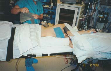
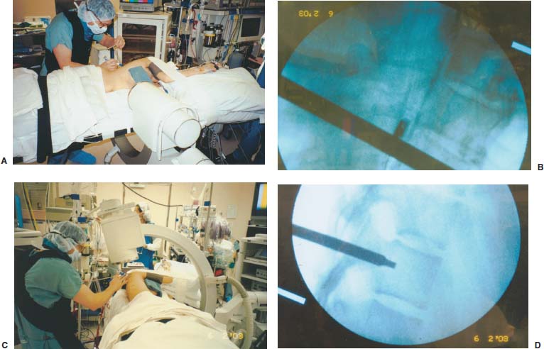
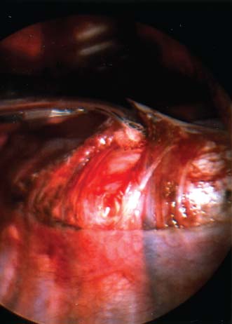
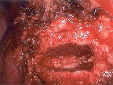
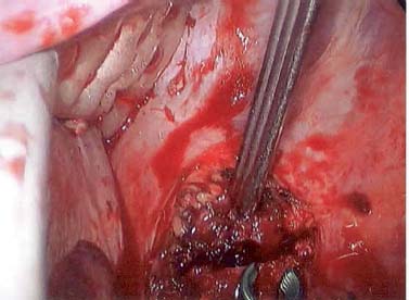
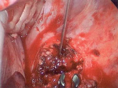
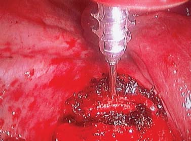
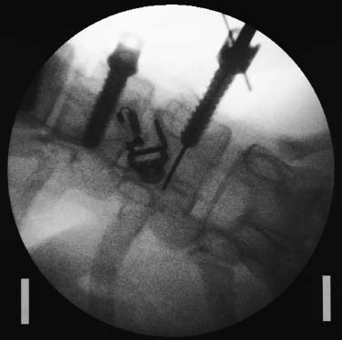
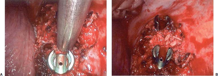
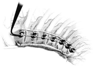
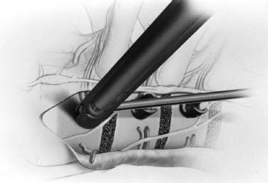
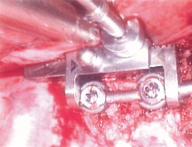
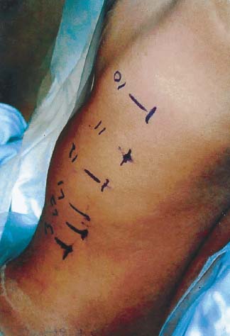
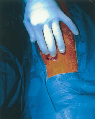
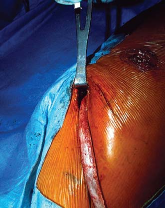
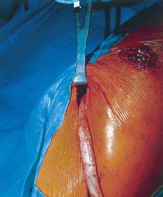
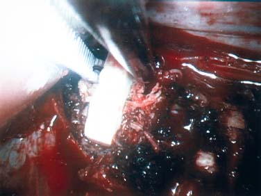
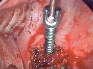
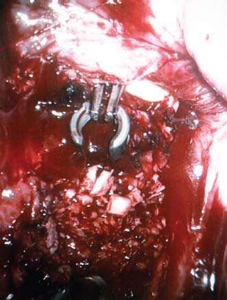
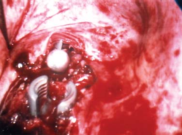
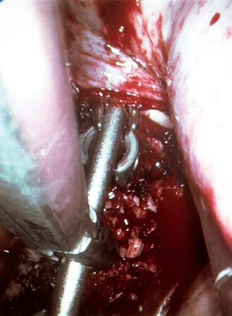
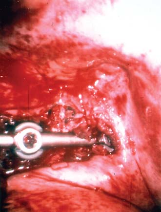
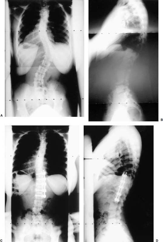
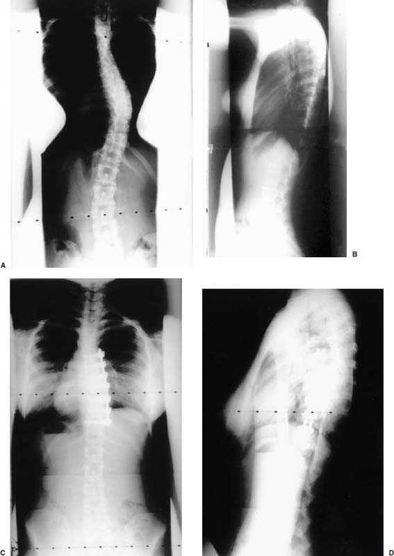
Endoscopic spine surgery has made many advances and improvements, from its inception with biopsy and diskectomy in the early 1990s, to the present, with instrumentation, correction, and fusion of deformity.1 Endoscopic or minimally invasive surgery has the advantage of improved visualization, decreased blood loss, decreased tissue trauma, decreased pain, and less time for rehabilitation; however, when performing endoscopic or minimally invasive surgery, one must adhere to the ultimate goals of the procedure to be performed and not do less because the incisions are smaller. One also must be well versed in the open technique before embarking on this endoscopic procedure. After extensive experience at the Kaiser Sacramento (California) Spine Center with thoracoscopic anterior release and fusion for scoliosis, kyphosis, hemiepiphyseodesis, and hemivertebrectomy, we embarked on the development of a technique for endoscopic instrumentation, correction, and fusion of primary thoracic curves. From our previous work and that of others, we documented the benefits of thoracoscopic surgery, which included improved visualization, improved access to the extremes of the curve, decreased blood loss, decreased operating times, shorter hospital stay, faster return to school and activities, and decreased overall costs.1,2 Our goal in developing an endoscopic technique for the treatment of scoliosis is to perform a safe, reproducible, and effective procedure that is comparable to or better than a formal open technique. Goals for scoliosis surgery continue to be the restoration of spinal alignment and balance in all planes, as well as axial derotation. At the Kaiser Sacramento Spine Center, we performed our first entirely endoscopic instrumentation, correction, and fusion for thoracic scoliosis in October 1996.3 The first few cases were performed with rudimentary implants and instrumentation. As we have gained experience with the surgical technique, and as improvements have been made in the implants and instrumentation, advances in the procedure have continued. Surgical Technique for Primary Thoracic Scoliosis Intraoperative Preparation Intraoperative somatosensory evoked potential (SSEP) and motor evoked potential (MEP) monitors are placed in standard fashion and checked. General anesthesia is administered with a double lumen intubation technique in adults and children weighing more than 45 kg. Children weighing less than 40 to 45 kg may require selective intubation of the ventilated lung. Once intubated, the patient is placed in the direct lateral decubitus position with the concave side of the curve positioned down. All bony prominences are checked and well padded. This body orientation provides a reference guide to estimate the direction of the anteroposterior and lateral guidewire and screw placement. The position is rechecked prior to beginning guidewire placement. The arms are both placed at 90 degrees to the body (Fig. 14–1). The hips and shoulders are secured to the operating table with tape to ensure correct body position throughout the procedure. The C-arm is utilized in the posteroanterior and lateral plane to mark the sites for portal placement (Fig. 14–2). The portal sites are cutaneously marked with a felt tip pen from the inferior to the superior ends of the Cobb angle. Two endoscopic monitors are necessary and are placed at the head of the operating table to allow visualization from both the anterior and posterior positions. The operating surgeon is positioned at the patient’s back to allow anatomic orientation of the external landmarks visualized through the endoscope. In addition, this position allows all instruments to be directed away from the spinal cord and enables the surgeon to place the screws in line with the spinal rotation safely. FIGURE 14–1 The patient is in the direct left lateral decubitus position. The arms and hips are taped onto the operating room table to maintain this position throughout the procedure. Incision and Portal Placement Following deflation of the lung, an initial 1.5 cm incision is made at the level of the sixth or seventh intercostal space in line with the spine. The portal placement accounts for spinal rotation as determined preoperatively under C-arm control. Placement of the initial portal at this level will avoid injury to the diaphragm, which maintains a more caudal position. Digital inspection of the portal is performed to ensure lung deflation and the absence of pleural adhesions. The endoscope is inserted into the initial portal and utilized for additional portal placement under direct visualization. The portals are positioned directly over the rib two interspaces apart, allowing access to two vertebral levels from a single incision by moving the portal above and below the rib. Three to five incisions are needed, depending on the number of levels to be instrumented. FIGURE 14–2 A The C-arm is placed in the posteroanterior plane at the distal level to be instrumented with a rod as a marker. A skin marker is used to notate the levels to be instrumented. (B) Posteroanterior C-arm image of the rod marker parallel to the end plates of the distal level. (C) Schematic drawing demonstrating the C-arm in position in the lateral plane using the rod marker to determine the portal location. (D) Lateral C-arm image demonstrating the rod marker at the level of the rib head; the portal will be made just anterior to this mark. FIGURE 14–3 Intraoperative view through the endoscope. The pleura has been incised along the midline of the vertebral bodies and is reflected off the anterior longitudinal ligament. Spine Exposure The pleura is incised longitudinally with electrocautery along the length of the spine to be instrumented. A hook electrocautery is placed on the pleura overlying an intervertebral disk, and a pleural opening is made. The pleura is elevated off the spine and incised. This maneuver allows for incision of the pleura along the spine segments to be instrumented and thus avoids injury to the segmental vessels. The pleura is further dissected anteriorly from the anterior longitudinal ligament and posteriorly from the rib heads (Fig. 14–3). An x-ray is obtained as the first disk is removed, and a small shaver is placed into the disk space to the opposite side. This allows for determination of the level and will confirm complete diskectomy. Diskectomy The intervertebral disk anulus is incised with the cautery. A complete diskectomy is performed using standard or custom curettes and Kerrison and pituitary rongeurs to expose the chondral end plates. The removal of the disk and anulus extends anteriorly to the anterior longitudinal ligament and posteriorly to just behind the rib heads (Fig. 14–4). The anterior longitudinal ligament is thinned to a flexible remnant with a pituitary rongeur from within the disk space. By thinning the anterior longitudinal ligament, it can no longer limit spinal mobility; however, it is able to contain bone graft. The chondral end plates are removed, and the bony end plates are rasped to a homogeneous bleeding surface. The disk space is packed with Surgicel to provide hemostasis. FIGURE 14–4 Intraoperative view through the endoscope of a diskectomy. The cartilage has been removed from the end plates, and the anterior longitudinal ligament has been thinned from inside the disk space. Bone Graft Harvest On completion of the diskectomies, the portals are removed, and attention is directed toward rib bone graft harvest. At the level of each incision the rib is subperiosteally exposed with sequential retraction as far anteriorly and posteriorly as possible. A perpendicular cut using the endoscopic rib cutter is made in the superior aspect of the rib at the anterior and posterior extent of the rib dissection. The cuts are connected, with a straight osteotome removing the superior portion of the rib. Multiple rib sections are removed in a similar fashion and morcellized until sufficient graft is available. This technique maintains the integrity of the rib as well as protecting the intercostal nerve and decreasing postoperative pain. Screw Placement Body position and rotation are checked. The sterilely draped C-arm is brought into the operating field, and the base is placed parallel to the superior most vertebral body to provide an accurate image. The portals and endoscope are replaced. The segmental vessels are cauterized at the midvertebral level. Larger segmental vessels and the azygous system may be ligated with endoscopic vascular staples and transected. FIGURE 14–5 Intraoperative view through the endoscope showing the K-wire guide inserted onto the vertebral body. The K-wire triple guide is placed centrally on the vertebral body and parallel to the end plates. The guide is placed anterior to the rib head, with a slight posterior to anterior inclination (Fig. 14–5). This position directs the wire away from the spinal canal, and the position can be monitored under biplanar fluoroscopic control. Once the guide is correctly aligned, a K-wire is advanced into the vertebral body, engaging the opposite cortex. Fluoroscopic monitoring is used to avoid penetration of the opposite cortex and potential penetration of the K-wire into the contralateral segmental vessels and lung (Figs. 14–6, 14–7). The screw length is measured on the scale at the upper section of the K-wire or determined by measuring the preoperative x-ray. The K-wire guide is removed, and the cannulated screw tap is advanced only into the near cortex of the vertebral body. If the use of a staple or a washer is desired, it can be inserted at this time. The K-wire is grasped to avoid cortical penetration during screw tap and screw advancement (Fig. 14–7). The appropriately sized screw is advanced over the guidewire, engaging the opposite cortex and seating the head against the valley of the vertebral body (Fig. 14–8). The guidewire is removed once the screw is advanced three fourths of the distance across the vertebral body. The screws can also be inserted without a K-wire or with image guidance. The rib heads are used as a reference for subsequent screw placement to ensure appropriate screw alignment, thus resulting in proper spinal rotational alignment. If each of the screws is placed in the same position of each vertebral body accounting for rotation, the screws will end in a V pattern and will aid in derotation of the spine during rod reduction. Screw depth placement must be accurate and at similar levels; otherwise, seating of the rod will be difficult. The screw depth can be checked with fluoroscopic guidance. FIGURE 14–6 Intraoperative view through the endoscope showing the K-wire inserted into the vertebral body. FIGURE 14–7 Intraoperative view through the endoscope showing the tap placed over the K-wire ready to be inserted into the vertebral body. FIGURE 14–8 Intraoperative view through the endoscope showing the K-wire guide inserted onto the vertebral body. FIGURE 14–9 (A) Intraoperative view through the endoscope showing the bone graft funnel inserted into the disk space. (B) Intraoperative view demonstrating a disk space filled with bone graft and graft placed over the adjacent vertebral bodies. Bone Graft Placement The Surgicel is sequentially removed from the intervertebral disk space prior to bone graft placement. The periosteum is incised anteriorly and posteriorly at each disk space. The periosteum is next elevated off the ends of the vertebral bodies. The end plates are rerasped, and the bone graft is delivered to the disk space using the graft funnel and plunger. The disk is partially filled, then a small tamp is used to push the graft to the opposite side to ensure complete filling of the space. Once the disk space has been filled, more graft is placed over the space and the adjoining area where the periosteum has been elevated (Fig. 14–9; this will allow for improved x-ray evaluation of the fusion postoperatively). Rod Length and Placement The rod length is measured with the endoscopic rod gauge, consisting of a fixed ball on the end of a flexible cable. The fixed ball is placed within the saddle of the inferior screw, and the end of the cable is then guided with a pituitary rongeur through the other screw heads to the superior screw. The cable is tightened, and the rod length is measured from the scale (Fig. 14–10). A 4.5 mm titanium rod is cut to the premeasured length and placed freely within the chest cavity through the inferior incision. The rod is placed flush into the inferior screw saddle. This is performed to avoid protrusion into or puncturing of the diaphragm. The plug introduction tube is placed over the screw head, temporarily securing the rod (Fig. 14–11). The plug inserter is advanced through the plug guide and the plug is inserted into the vertebral screw, thus securing the rod to the vertebral screw. The inferior screw is the only plug that is initially completely tightened. The rod is next sequentially reduced into the saddles of the remaining screws with the rod pusher, and plugs are placed but not tightened. FIGURE 14–10 Schematic view of the screws in place, with the endoscopic rod measurer inserted through all of them. The rod length is determined by reading the scale at the top of the measurer. FIGURE 14–11 Schematic diagram of the rod as it is inserted into the most inferior screw, with the plug introduction tube over the screw. The window at the tip of the tube on the screw shows the plug inserted into the screw. Rod Compression Once the rod is in place and the plugs are provisionally inserted, compression between each screw is performed. The compressor is placed freely into the chest cavity and over the screw heads on the rod at the inferior end of the construct. Turning the driver clockwise to bring the two screws closer together performs compression. Segmental compression is sequentially performed from inferior to superior until all levels have been compressed (Fig. 14–12). A cable compressor is available as another option. The construct is visualized, the chest cavity is irrigated, and the lung is inflated under visualization of the endoscope to confirm that the entire lung is reinflated. A chest tube is placed through the inferior portal, and the incisions are closed in layers in standard fashion. FIGURE 14–12 Intraoperative view via the endoscope, with the endoscopic compressor on the rod compressing two screws together. Surgical Technique for Instrumentation, Correction, and Fusion of Primary Thoracolumbar Scoliosis As the thoracic endoscopic technique evolved and our results began approaching that of the formal open technique with primary thoracic scoliosis, we proceeded to our next challenge4: to treat thoracolumbar scoliosis via a minimally invasive endoscopic approach. This endeavor, however, presents several new challenges that are not issues with the thoracic spine. The major challenges are endoscopically crossing the diaphragm and maintaining retroperitoneal exposure, especially after an opening has been made under the diaphragm. These goals need to be met, in addition to attaining lumbar lordosis and anterior column support. General anesthesia is administered as in the thorascopic approach with a double lumen intubation. Once intubated, the patient is placed into the direct lateral decubitus position with the arms at 90/90. The hips and shoulders are then taped to the operating table. This will help to maintain the patient’s correct positioning throughout the case. The C-arm is again used as in the thoracoscopic technique; however, each level to be instrumented is marked on the skin for reference (Fig. 14–13). Once the lung has been deflated, the proximal portal is inserted in line with the spine, positioned according to the amount of spinal rotation. Inserting the first portal at this level will help avoid injury to the diaphragm. Once the portal is made, digital inspection of the portal is performed to ensure that the lung is deflated and that no adhesions exist. The endoscope is then inserted into the chest, and additional portals are placed under direct visualization. FIGURE 14–13 Photograph of a patient with skin markings for a T10–L3 minimally invasive instrumentation correction and fusion. Three portals are needed in the thoracic cavity: a working portal, a second for the endoscope, and a third for retraction of the lung and diaphragm. Once the portals have been inserted and the scope introduced, the apex of the chest is visualized, and the ribs are counted caudally to the desired level. The hook bovie is placed on the pleura over a disk, and an opening is made. The hook is then inserted under the pleura, and the pleura is elevated and incised longitudinally in the midvertebral body, as in the thoracic technique. The pleura is then dissected anteriorly off the anterior longitudinal ligament and posteriorly off the rib heads. A marker is placed into one of the disks to be removed, and a localization x-ray is obtained. The electrocautery is then used to incise the disk anulus. The disk is removed in standard fashion, using various endoscopic curettes, and pituitary, Cobb, and Kerrison rongeurs. Once the disk is completely removed, the anterior longitudinal ligament is thinned from within the disk with a pituitary rongeur. The ligament is thinned to a flexible remnant that is no longer structural, but will contain the bone graft. The disk and anulus are posterolaterally also completely removed. Once the disk has been evacuated, the end plate is completely removed, and the disk space is inspected directly with the scope. The end plates are rasped to a homogeneous bleeding surface. The disk space is then packed with Surgicel to control end plate bleeding. All thoracic disks are removed in this fashion, as described in the thoracic technique. The T12–L1 disk may also be removed from the thoracic cavity, depending on where the diaphragm inserts. If the diaphragm inserts below the T12–L1 disk space and the exposure of the disk does not require taking down any of the diaphragm, the disk must be removed from the thoracic approach. On the other hand, if the diaphragm inserts above the T12–L1 disk, the disk must be removed from the retroperitoneal approach below the diaphragm. The scope, instruments, and portals are removed at this time. The anesthesiologist can be instructed to reinflate the lung, and the retroperitoneal approach is performed. The lumbar retroperitoneal incision is performed over the previously marked skin site via an eleventh rib approach. If the planned instrumentation is extending to the L2 level, then the skin mark should be placed over the L1–L2 disk space. This will allow for excellent access from the T12–L1 disk space to the L2 vertebral body. If the hardware is to extend to L3. the incision is placed directly over the center of the L2 vertebral body to allow access from the L1 vertebral body to the L3 vertebral body. If the hardware is to extend to L1, we can perform a retroperitoneal approach over the T12–L1 disk space; however, the approach to L1 is always attempted through the thoracic cavity first. To date, we have been able to approach L1 through the thoracic cavity on every attempt, although this may require extensive retraction of the diaphragm. FIGURE 14–14 Photograph of the 4 cm skin incision for the retroperitoneal approach placed over the body of L2. A 3 to 4 cm incision is performed over the predetermined location to expose the eleventh rib (Fig. 14–14). The eleventh rib is exposed by moving the incision as far anterior and posterior as possible (Fig. 14–15). Once the rib has been subperiosteally dissected, it is removed with the endoscopic rib cutter. This is performed by freeing the rib anteriorly from the soft tissue, placing the jaw of the rib cutter under the rib and the foot over the top, then sliding the rib cutter posteriorly along the rib as far as possible. Once this is done, the rib is amputated. Using this technique, virtually the entire rib can be harvested for bone graft (Fig. 14–16). Dissection is carried through the muscle into the retroperitoneal space and onto the psoas. The peritoneum is then reflected off the psoas, spine, and diaphragm. Next, lighted Deaver retractors are inserted. The psoas is retracted posteriorly, and the disks and end plates are exposed and removed in the standard fashion. We have tried several different exposure techniques, and this approach appears to work the best. Other techniques have been problematic. The balloon technique can work, but the balloon can pop or can get in the way of the operative site. The laprolift can be bulky and obtrusive, and it can interfere with the C-arm. The CO2 technique requires a closed system, and once the diaphragm has been crossed, the pneumoperitoneum and exposure are lost. FIGURE 14–15 Photograph of the retroperitoneal incision with exposure of the eleventh rib. FIGURE 14–16 Photograph of the retroperitoneal incision. The eleventh rib has been amputated at its cartilaginous junction. With the endoscopic rib cutter, the rib can now be amputated at the rib head. FIGURE 14–17 Intraoperative view of the retroperitoneal approach. A femoral ring filled with autograft is inserted into the L1–L2 disk space. To the left of the femoral ring is the diaphragm, and above the femoral ring is the peritoneum. Once all the disks have been removed, more rib graft can be harvested from the thoracic portal sites, as described in the thoracic technique. After the graft has been obtained, the disk spaces from the lower thoracic through the lumbar are sized. Femoral ring allograft is cut and contoured into a tapered shape to produce lordosis. Once the femoral ring has been contoured, the center is packed with the morcellized rib graft and impacted into the disk space (Fig. 14–17). Morcellized graft is inserted into the disk space prior to placement of the femoral ring and then over the ring once in place. This is performed at each of the lumbar levels, decreasing the amount of taper of the grafts as they are placed proximally. At times, the lower thoracic vertebrae are smaller than the femoral rings. Humeral ring allograft can be used in these situations. An alternative to femoral or humeral allograft is cages. Both provide anterior column support and can be used to produce lordosis. The C-arm is now placed into the operating field and positioned at the superior most vertebral body. It is imperative to have the C-arm parallel to the spine to give an accurate image. The undisturbed segmental vessels are grasped at the midvertebral body level and are ligated with the electrocautery. The vessels are located in the valley or middle of the vertebral body and serve as an anatomical guide for screw placement. FIGURE 14–18 Intraoperative view through the endoscope showing a screw placed over the K-wire ready to be inserted into the vertebral body. The body position and rotation are again checked. The K-wire guide is placed onto the vertebral body just anterior to the rib head. The position is checked with the C-arm to ensure that the wire is parallel to the end plates and in the center of the body. Next, the inclination of the guide is checked in the lateral plane by examining the chest wall and the rotation. The guide should be in a slight posterior to anterior inclination, directing the wire away from the spinal canal. A lateral C-arm image should be obtained if there is any doubt or concern. Once the correct alignment of the guide has been attained, the K-wire is inserted into the appropriate cannula and drilled into the vertebral body parallel to the end plates. The position is confirmed with the C-arm as the wire is inserted. The guide is removed, and the tap is placed over the K-wire at the top of the guide. The wire is grasped with a clamp and held into position as the tap is inserted so the wire will not advance. The tap is slightly undersized, and only the near cortex is tapped. The appropriately sized screw is placed over the wire and advanced (Fig. 14–18). The screw should penetrate the opposite cortex for bicortical fixation. The screws should be seated into the valley of the vertebral body. Using the rib heads as a reference for subsequent screw placement helps to ensure the screws are in line and yield proper spinal rotation. If each of the screws is placed in the same position of each vertebral body accounting for rotation, the screws will end in a V pattern and will aid in derotation of the spine during rod reduction. The sidewalls of the screws (saddles) are adjusted in line for receipt of the rod. The screw heads need to be aligned so that the screws align in an arc. If a screw is inserted more than a few millimeters deeper than the rest of the screws, reduction of the rod into the screw head may be difficult. The C-arm image can clearly show depths as the screws are being inserted. Once all the screws have been placed, the Surgicel is removed from the upper thoracic disk spaces. The end plates are rerasped, and the graft is inserted. The graft is delivered to the disk space using the graft funnel and plunger. The disk space should be completely filled to the opposite side. FIGURE 14–19 Intraoperative view through the endoscope showing the right-angle clamp under the diaphragm with the tips in the T12 screw. All work has been performed on both sides of the diaphragm without its detachment until this point in the procedure. The diaphragm must now be crossed to obtain the rod length and perform the remainder of the procedure. With the endoscope in the chest cavity visualizing the diaphragm where it attaches to the spine, a right-angle clamp is inserted through the retroperitoneal incision. The right-angle clamp is used to make a small opening under the diaphragm at the center of the vertebral body (Fig. 14–19). The opening is made under direct endoscopic visualization and is only made large enough to permit the passage of the rod measurer, the rod, and the compressor arm. The rod length is determined with the endoscopic rod measurer. The fixed ball at the end of the measuring device is placed into the saddle of the inferior screw. The ball at the end of the cable is then guided through the screws and the small opening under the diaphragm with a pituitary to the most superior screw and inserted into the saddle of the superior screw (Fig. 14–20). The wire is then pulled tight, and a reading is taken from the scale. The 4.5 mm rod is cut to length and inserted into the chest cavity through the most inferior port, then manipulated superiorly until the rod is inside the chest cavity. The right-angle clamp is inserted into the retroperitoneal incision and under the diaphragm. The rod is placed into the jaws of the right-angle clamp and pulled into the retroperitoneal space (Fig. 14–21). FIGURE 14–20 Intraoperative view through the endoscope showing the ball end of the endoscopic rod measurer coming through the small opening under the diaphragm. FIGURE 14–21 Intraoperative view through the endoscope showing the right-angle clamp under the diaphragm grasping the rod and pulling it into the retroperitoneal space. The rod is manipulated into the inferior screw flush with the saddle. Once the rod is in place, the plug introduction tube is placed over the screw to guide the plug and hold the rod in position. The plug inserter is placed through the plug introduction tube, inserted into the screw, and torqued. This is the only plug that is initially tightened completely. The rod is then sequentially reduced with the rod pushers. The plugs are inserted as the rod is reduced and provisionally tightened. Compression between the screws is performed once the rod has been seated and all plugs inserted. The compressor is inserted through the retroperitoneal incision. The compressor fits over the screw heads on the rod, and compression is accomplished by turning the compressor driver clockwise and compressing the two screws together. Compression is started at the inferior end of the construct with the most inferior screw fully tightened. Compression is sequentially performed from caudal to cranial. When the diaphragm is reached, the endoscope is reinserted into the chest cavity, and the long arm of the compressor is manipulated under the diaphragm and over the next screw head. Compression is performed at this level. The compressor is now removed and inserted into the chest cavity. Compression is sequentially performed superiorly until all the remaining levels have been compressed (Fig. 14–22). A chest tube is placed through the inferior portal, and the incisions are closed in layers in standard fashion. FIGURE 14–22 Intraoperative view through the endoscope demonstrating the construct going through the small opening under the diaphragm, as the diaphragm is tented over the construct. FIGURE 14–23 Anteroposterior (A) and lateral (B) preoperative x-rays of a 14-year-old female with a 26-degree T5–T10, 54-degree T10–L2, and 32-degree L2–L5 curve. Postoperative anteroposterior (C) and lateral (D) views of the same patient after a minimally invasive instrumentation, correction, and fusion with the new dual-head screws. FIGURE 14–24 Anteroposterior (A) and lateral (B) preoperative x-rays of a 14-year-old female with a 48-degree thoracic and 25-degree lumbar curve. Postoperative anteroposterior (C) and lateral (D) views of the same patient after an endoscopic instrumentation, correction, and fusion with the new dual-head screws. Postoperative Care Anteroposterior and lateral x-rays are obtained, and the patient is transferred to recovery. The patient stays in ICU overnight, and is then transferred to a regular floor. The patient is fitted for a custom thoracolumbosacral orthosis, which is worn for 3 months. The chest tube is removed when the drainage is less than 75 ml per shift, usually on postoperative day 2. The patient is ambulated the day the chest tube is removed and discharged when independent with ambulation, generally postoperative day 3. Patients are seen, x-rayed, and assessed at months 1, 3, 6, and 12 postoperatively. Discussion The development of the endoscopic technique of instrumentation, correction, and fusion of scoliosis has been an evolution, and the technique has undergone several modifications since our initial cases. The endoscopic treatment of thoracolumbar scoliosis has brought about a new set of challenges, many of which are explored in this chapter. As our preliminary work has shown, several basic principles must be adhered to, with the result that this minimally invasive approach does not necessarily equate to “minimal” or “less” surgery. The key to successful fusion is a total diskectomy and complete end plate removal. Sagittal balance and anterior column support are critical in treating thoracolumbar scoliosis. This can be addressed with contoured femoral ring allograft or cages. We have used a 4.5 mm titanium rod in our initial series, with no rod complications noted to date. Because of concern of rod size, however, especially with thoracolumbar scoliosis, we have developed a unique screw design: the dual-head screw. This distinctive design allows the flexibility of a single rod for easy endoscopic manipulation and for those curves that do not require such a powerful reduction. The first rod is inserted and the spine reduced, then the second rod is dropped into place. In those cases in which a greater reduction is required, both rods can be reduced simultaneously. In each case the end result is a two-rod construct, with the placement of only one screw. With this design we are able to place a 7.5 mm screw with a smaller staple into the upper thoracic vertebral body and an 8.5 mm screw and staple into the lower thoracic and lumbar spine. The result is the versatility of a somewhat flexible rod easily reduced endoscopically, with the benefit of a more rigid end construct with greater torsional stability. This screw design now allows a straightforward endoscopic alternative for the placement of a dual rod. With a dual rod-dual screw construct, the screws must be placed divergent, which is very difficult endoscopically, if not impossible. With the dual-head screw, however, the same central trajectory is used as with the standard single-screw placement. Other advantages of this screw design are the inherent stability each screw offers, acting like a cross-link, thus avoiding the difficulty and expense of endoscopically placing cross-links. The dual-head screw can be easily placed into smaller vertebral bodies, which cannot support a two-screw construct. Another benefit is the smaller size of the dual-head screw versus that of a dual screw—dual rod construct (Figs. 14–23, 14–24). The preliminary results for the endoscopic treatment of thoracic and thoracolumbar scoliosis show promising trends. As decreasing surgical times continue to be accompanied by acceptable fusion rates and curve correction, investigation of this approach continues to proceed. The observed advantages for patients, including shorter hospitalizations and rehabilitation periods and decreased pain, strengthen the case for continued evaluation and follow-up of this technique. REFERENCES 1. Regan JJ, Mack MJ, Picetti GD III. A comparison of VAT to open thoracotomy in thoracic spinal surgery. Paper presented at: Annual Meeting of the Scoliosis Research Society; September 18–23, 1993; Dublin, Ireland. 2. Picetti GD III. Video-assisted thoracoscopy (VATS) in the treatment of congenital hemivertebra. Paper presented at: Annual Meeting of the Spine Society of Australia; September 8,1996; Cairns, Australia. 3. Picetti GD III, O’Neal K, Estep M, et al. Correction and fusion of thoracic scoliosis using an endoscopic approach. Paper presented at: Annual Meeting of the Scoliosis Research Society; September 24, 1997; St. Louis, MO. 4. Picetti GD III, Ertl J, Bueff HU. Endoscopic instrumentation, correction and fusion of thoracic idiopathic scoliosis. Spine. 2001;1: 190–197.
14

Minimally Invasive Instrumentation, Correction, and Fusion of Primary Thoracic and Thoracolumbar Scoliosis

< div class='tao-gold-member'>
Related posts:
 Fluoroscopic Image-Guided Spine Surgery
Intradiskal Electrothermal Therapy
Gasless Endoscopic ALIF: The BERG Approach
Combined Prone Position Thoracoscopic Anterior Release and Posterior Instrumentation for Deformity Surgery
Anterior Endoscopic Cervical Microdiskectomy
Percutaneous Vertebroplasty for Painful Vertebral Body Compression Fractures
Fluoroscopic Image-Guided Spine Surgery
Intradiskal Electrothermal Therapy
Gasless Endoscopic ALIF: The BERG Approach
Combined Prone Position Thoracoscopic Anterior Release and Posterior Instrumentation for Deformity Surgery
Anterior Endoscopic Cervical Microdiskectomy
Percutaneous Vertebroplasty for Painful Vertebral Body Compression Fractures


