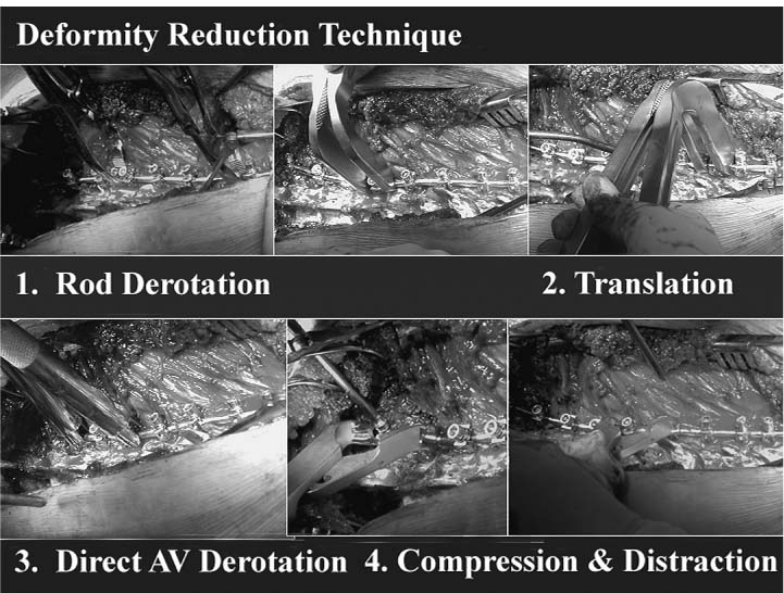
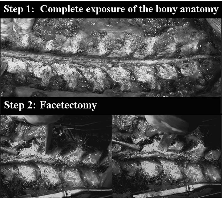
Chapter 16 Since the introduction of the Harrington Rod Instrumentation System (hooks and distracting rods) in the late 1950s,1 spinal instrumentation has evolved in an effort to maximize correction and stabilization. Advances have been made toward trying to obtain balanced correction, to save more motion segments, and to get patients back to their previous daily activities more quickly with less reliance on bed rest, casting, or bracing. The next step in the evolution was using two rods for a thoracic curve and achieving segmental fixation with sublaminar wires. Luque2 introduced segmental fixation using sublaminar wires in the 1970s and Drummond et al.3 subsequently modified the Luque technique by using segmental wiring through the base of the spinous process (Wisconsin wiring technique). In the early 1980s, the Cotrel-Dubousset (CD) spinal instrumentation system was introduced.4 CD instrumentation using multiple hooks with both rods became a new standard of posterior spinal instrumentation in an effort to get even stronger fixation and to “derotate” the spine to optimize three-dimensional correction. This original CD instrumentation technique has evolved into several hybrid variants: (1) hook anchors at the top and the bottom of the curve with Wisconsin wires in between; (2) hook anchors at the top and pedicle screw anchors at the bottom of the curve with sublaminar wires in between; (3) proximal hook anchors and distal pedicle screw anchors. CD instrumentation allows distraction, compression, translation, lordosing, and kyphosing forces for deformity correction. Biplane correction (coronal and sagittal) of the deformity became possible using CD instrumentation (Fig. 16–1). The next evolutionary phase for posterior treatment has been that of using pedicle screws more liberally throughout the thoracic and upper lumbar spine.5–11 As spinal instrumentation and surgical techniques in addition to experience of surgeons have evolved, pedicle screw fixation in the thoracic spine can be safely placed reducing the possibility of short-term (neurovascular or visceral damage) and long-term complications (curve progression, crankshaft phenomenon, coronal or sagittal imbalance, loss of fixation, implant failure, or pseudarthrosis).5–11 The benefits of using pedicle screws instead of hooks or sublaminar wires are many: three-column fixation allows better pull-out strength and greater control in the sagittal, coronal, and rotational planes due to increased stability to axial, bending, and rotational forces. Additionally, fewer vertebral motion segments may need to be arthrodesed and should lessen or obviate the need for postoperative bracing. Other benefits include secure fixation after a laminectomy, when the posterior elements are otherwise incompetent, and the ability to treat three-column injuries with adequate stability. In patients with spinal deformities, segmental pedicle screw fixation has demonstrated greater three-dimensional correction with decreased rates of curve progression and higher fusion rates.4–11 Recently, Luhmann et al.12 demonstrated that posterior segmental pedicle screw instrumentation and fusion in patients with thoracic adolescent idiopathic scoliosis (AIS) curves from 70 to 100 degrees had equal coronal correction with anterior and posterior segmental spinal fusion. The apical vertebrae can be derotated to enhance correction and potentially prevent the need for a thoracoplasty.13 Our preliminary results demonstrated that direct bilateral apical vertebral derotation (BAVD) techniques using pedicle screws increase the percent-predicted pulmonary function test (PFT) results.13 Also, the flexibility of multiple screw types and stability of the screw anchor allows easier connection to the rods. Various hook and wire fixation techniques can be applied in addition to pedicle screws depending on local anatomy and surgical indications. Despite the potential benefits, many surgeons have avoided placing pedicle screws especially in the thoracic spine because of their concern for neurologic, vascular, and visceral complications.14–18 The smaller size of the vertebral body and pedicles, variable pedicle insertion angles, and requirements for more precise screw placements, due to nearby neural and vascular structures, add to concerns regarding this technique. Rinella et al.19 demonstrated nearly 180% pedicle expansion (compared with preoperative internal diameter of the pedicle) after pedicle screw placement in a pediatric cadaveric spine. Complications can be minimized by using the free-hand anatomic technique described in this chapter with appropriate somatosensory evoked potential (SSEP), motor evoked potential (MEP), and triggered electromyogram (EMG) neurophysiologic monitoring techniques.10–13,19–24 At our institution, more than 10,000 thoracic pedicle screws (750 patients, range 2 to 79 years) have been used as a primary fixation without any neurologic, visceral, or vascular complications or revision surgery needed at up to 13 years follow-up. Figure 16–1 Various deformity-reduction techniques. The indication for surgery due to AIS is a 45- to 50-degree thoracic curve. In addition to this coronal major Cobb angle, physical appearance such as shoulder balance, rib hump, patient and parents’ acceptance of the patient’s physical appearance, and skeletal maturity should be considered. The Lenke et al.25 classification simplifies and clarifies the decision-making process by including all curve types and sagittal plane measurements. The first principle is to differentiate the Lenke Type 1 (single thoracic) and 2 (double thoracic) curves from other curve types. The sagittal T2-T5 kyphosis (angle between the upper end plate of T5 and the lower end plate of T2) ≥20 degrees implies a “compensatory and structural” proximal thoracic cure regardless of the coronal flexibility measurements and is included in the fusion area.26 The sagittal T10-L2 kyphotic angle (angle between the upper end plate of T10 and the lower end plate of L2) ≥20 degrees is also very important to differentiate a thoracic curve from a double-major curve irregardless of the coronal flexibility measurements of the thoracolumbar/lumbar curve and is included in the fusion area.26 Thoracolumbar sagittal kyphotic angle, ligament laxity, and remaining growth potential must be considered to prevent postoperative distal junctional kyphosis (DJK). The second principle is to fuse selectively (selective fusion). Specific measurement ratios must be considered with minor curve flexibility measurements close to the 25-degree threshold. When analyzing main thoracic (MT) and thoracolumbar/lumbar (TL/L) curves, the relative apical vertebral translation (AVT), apical vertebral rotation (AVR), and Cobb angle measurements ratios should be considered. The thoracic AVT is the distance from the center of the vertebral body at the thoracic apex to the C7 plumbline. Similarly, the TL/L AVT is measured from the center of the lumbar apical vertebral body to the center sacral line (CSL). The CSL is measured as the vertical line from the center of S1 regardless of pelvic position. When the patient is perfectly balanced, the C7 plumbline and CSL are the same. The AVR is based on the Nash-Moe rotation index including half sizes as appropriate. For thoracic major curves, all three ratios (main thoracic/TL) >1.5 implies a false double-major pattern so selective fusion of only the thoracic curve should be strongly considered. When fusing only the major thoracic curve, the remaining angle of the major curve should be similar to the final angle of the compensatory curve, the supine lumbar curve, or push-prone lumbar curve. The third principle is how to decide the uppermost instrumented vertebra. To determine the proximal end point of the fusion, the position of the shoulders, the flexibility and size of the proximal thoracic (PT) curve, and the anticipated amount of main thoracic correction must be considered. When the PT curve is relatively inflexible, a supine or push-prone radiograph demonstrates contralateral shoulder elevation, or the preoperative clinical position of the contralateral shoulder is high, we will usually fuse the proximal curve to T2. By “contralateral shoulder,” we mean the shoulder opposite the main curve, that is, left shoulder for a right thoracic curve or right shoulder for a left lumbar curve. When the PT curve is somewhat flexible or the shoulders are in neutral position, we will consider fusing to T3; whereas with flexible PT curves or with a low contralateral shoulder we typically fuse to T4. The fourth principle is deciding the lowest instrumented vertebra (LIV). The stable vertebra27 is the vertebral body that the CSL bisects. This lower end point is considered “safe” with hook instrumentation systems. The LIV in the hook group (n = 146) was 0.29 above the stable vertebra, and the LIV in the pedicle screw group (n = 48) was 0.67 above the stable vertebra in 194 consecutive AIS Lenke Type 1 and 2 patients in one study.27 Now we frequently can stop one to two levels short of the stable vertebra depending on rotation, curve magnitude, flexibility, coronal and sagittal balance, and so forth. In most of our recent cases with pedicle screw constructs, the LIV is the most proximal lumbar vertebra in which the center CSL touches any aspect of the vertebral body. Review of supine, push-prone, and lateral benders provide a sense of postoperative balance. Is there any difference between the DJK in a fusion ending at T12 versus L1 in AIS undergoing segmental posterior spinal instrumentation? Thirty-nine AIS patients who underwent a posterior spinal fusion (PSF) with a T12 LIV (T12 group) were compared with 76 patients who underwent a PSF with an L1 LIV (L1 group). Abnormal DJK was defined by the distal junction disk angle between the lower end plate of the LIV and the upper end plate of the infra-adjacent vertebra, which was at least 5 degrees greater than the preoperative measurement and also at least 5 degrees greater than the normal disk angle. The disk angle beneath the LIV (LIVD) demonstrated similar changes (6.9 to 3.7 degrees in the T12 group and 7.3 to 2.8 degrees in the L1 group, p = 0.459). The average disk height change beneath the LIV demonstrated similar changes (0.6-mm decrease in the T12 group and 0.7-mm decrease in the L1 group). The incidence of DJK as defined was 10 cases (2/39, 5% in the T12 group and 8/76, 11% in the L1 group) (p = 0.324). No patient complained of symptoms related to the DJK.28 The LIV should be correctly tilted to allow smooth transition into the compensatory lumbar curve. For Type A lumbar modifiers in the Lenke et al. system, the distal end plate of the LIV can often be corrected to horizontal. Mild tilt is allowed for the LIV of Type B lumbar modifiers. For Type C lumbar modifiers, an appropriate degree of tilt must be maintained. A rough estimate is the remaining tilt on the supine and bending radiographs, although intraoperative radiographic analysis is equally important. The planned LIV tilt on the preoperative supine radiograph is a good reference point but it is not necessarily the rule. The decision to approach the curve with an anterior and/or posterior fusion depends on a variety of factors including the size and “personality” of the major curve, the characteristics of the compensatory curves, the patient’s sagittal balance, and the patient’s performance on pulmonary function tests.29 Our typical fusion levels for anterior-only approaches to a Lenke Type 1 curve are between the upper and lower end vertebrae.30 Advantages to anterior-only instrumentation are generally shorter fusion levels, no disruption of the posterior extensor musculature (less junctional problems), and convex compression curve correction.31 We typically use dual rod systems and approach the spine from the side of the convexity of the curve. Occasionally, a single rod endoscopic (VAT) approach will be used in smaller patients with flexible thoracic curves. As noted previously, our posterior-only fusion levels depend on a variety of factors, but we can usually stop a level or two short from the distal stable level depending on our flexibility assessment. When the fusion levels are equivalent based on anterior and posterior fusion assessments (or the LIVs are equivalent and the UIVs are reasonably close), we tend to prefer posterior approaches because recovery is generally easier, and there is no chest wall violation. The corrective power of all-pedicle screw constructs have dramatically altered our operative approach and have increased the number of posterior-only procedures at our institution. In adolescents, we can typically approach curves ≤120 degrees with a posterior-only, all-pedicle screw construct. Very large curves (major Cobb angle >120 degrees) may require perioperative or intraoperative halo or halo-femoral traction in addition to a formal anterior or posterior vertebral column resection with preservation of segmental vessels and adjacent level diskectomy and fusion through open thoracotomy or thoracolumbar approaches to prevent irreversible spinal cord paraplegia.32 The “free-hand” technique is equivalent for lumbar and thoracic pedicle screw placement. No imaging is needed after initial localization films until all of the screws are placed. After initial exposure, each step is repeated sequentially at each level to be instrumented. If necessary, hooks or sublaminar wires can still be used after the screws are placed. A meticulous exposure of the posterior elements to be fused is critical to successful screw insertion. The dissection should be limited to only the fusion levels to limit soft-tissue disruption and reduce the potential for junctional kyphosis or transition syndromes. Usually, the proximal junctional dissection is a bit more difficult. We aim to place pedicle screws at the most proximal and distal vertebrae without disrupting the facet capsules, supraspinous and interspinous ligaments, and ligamentum flavum either proximally or distally. The spine is exposed to the tips of the transverse process bilaterally staying strictly subperiosteal to reduce bleeding (Fig. 16–2). The facet joints must be thoroughly cleaned and partially osteotomized to enhance visualization and fusion. The inferior 3 to 5 mm of the inferior facet and articular cartilage on the superior facet are removed except for the lowermost instrumented vertebra. It is essential to completely expose the base of the superior articular process as it is an important landmark to the ventral pedicle (Fig. 16–3).
Posterior Surgery for Thoracic Scoliosis
♦ Indications for Surgical Treatment of Thoracic Scoliosis
♦ Selection of Fusion Levels
♦ Selection of Posterior versus Anterior
Approach to Spinal Fusion
♦ Surgical Treatment
“Free-Hand” Technique for Pedicle Screw Placement
1. Incision and Exposure
2. Facetectomy
3. Starting Point
Related posts:
 Flexible versus Fixed Spinal Deformity
 Anterior/Posterior (AP) Surgery for Spinal Deformity
 Anatomical Variants with Spinal Deformity
 Anterior Surgery for Adolescent Thoracolumbar and Lumbar Scoliosis
 Technological Advances in Spinal Deformity Surgery
 The Lenke Classification System for Adolescent Idiopathic Scoliosis
Stay updated, free articles. Join our Telegram channel

Full access? Get Clinical Tree


