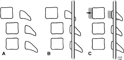
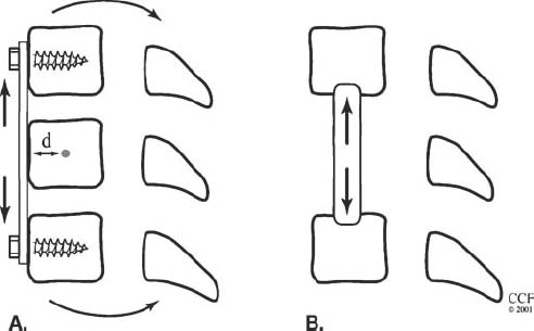
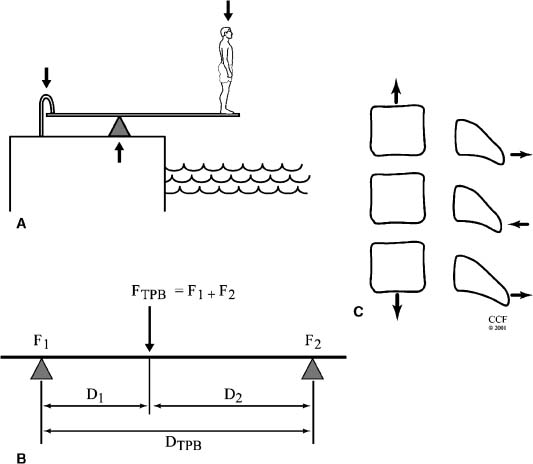
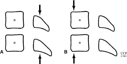
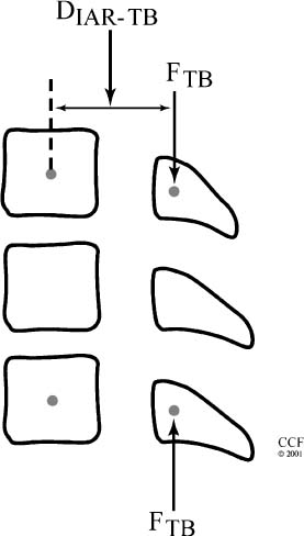
14 The spine is a mechanical structure complete with levers (vertebrae), pivots (facets and intervertebral discs), passive restraints (ligaments), and activators (muscles).1 Thus, a thorough understanding of spinal biomechanics is requisite to resect spinal tumors and to reconstruct the spine. Homeostasis of the spine can be disrupted by the direct effects of a tumor or by iatrogenic destruction of spinal integrity through surgical intervention. Spinal surgery can be destabilizing by disrupting bony integrity, by destroying spinal ligaments, by altering the bone-muscle interface, or by deinnervation. In terms of the spinal structures subject to violation, the anatomic corridor differs for ventral and dorsal surgical approaches. Therefore, stability is affected in different ways. Biomechanically, significant instability can be compensated for by one or a combination of three therapeutic maneuvers: (1) nonoperative conservative management (e.g., bracing), (2) restoration of the integrity of the ventral column through placement of a bony strut or instrumentation, or (3) placement of dorsal instrumentation. To facilitate understanding the biomechanical issues that must be considered when resecting spinal tumors and reconstructing the spine, how implants are used to stabilize the spine is examined first. Next, problem-based decision making and how it can be used to help develop solutions to complex biomechanical problems through a stepwise approach is discussed. Finally, more radical surgical approaches are explored through the clinical examples of spondylectomy. Reconstructing the spine after tumor resection typically requires the application of an implant. To design a successful construct mandates understanding the biomechanical forces applied to the spine by the implant. In reality, the resultant force vectors are often extremely complex. Fortunately, these forces can be broken into component force vectors to facilitate understanding while maintaining an accurate first-order approximation. When designing a construct, two fundamental biomechanical concepts form the framework for understanding how implanted forces interact with the spine: the instantaneous axis of rotation (IAR) and the neutral axis.2 The IAR is the axis about which each vertebral segment rotates at any given time. When a force is applied a finite distance (known as the moment arm) from the IAR perpendicular to the long axis of the spine, a bending moment is created (Fig. 14-1A). The power of the bending moment can be used to correct a deformity and to restore stability. Conversely, deformation is minimal and axial loading is the primary concern, so a graft should be placed in line with the neutral axis (Fig. 14-1B). Spinal instrumentation applies forces to the spine by one or more of the following mechanisms: (1) simple distraction, (2) three-point bending, (3) tension-band, (4) fixed moment arm cantilever beam, (5) nonfixed moment arm cantilever beam, and (6) applied moment arm cantilever beam. All of these mechanisms can be implemented through ventral, dorsal, or lateral approaches. FIGURE 14-1 (A) The application of a distraction force to the ventral aspect of the vertebral body (ventral to the neutral axis) results in a construct configured like a cantilever with the application of a moment arm. (B) The application of a distraction force to the midregion of the vertebral body (in the region of the neutral axis) buttresses the spine, without application of a moment arm. d, moment arm; straight arrows depict implant force applications; curved arrows depict bending moments. As mentioned earlier, a force applied at a distance perpendicular to the IAR creates a bending moment. Simple distraction is usually applied through ventral interbody or dorsal strategies. A ventral implant aligned with the neutral axis is positioned to resist axial loads without producing a bending moment; however, if the graft is placed ventral to the neutral axis, extension will result. A dorsally placed distraction force would tend to promote kyphosis and thus has little clinical application by itself; however, it can be combined with a three-point bending instrumentation, in which the central, ventrally directed force acts as a fulcrum. Three-point bending constructs usually involve the placement of dorsal instrumentation, typically over five or more segments. The two ends of the implant impart dorsally directed forces, which are balanced by a ventrally directed force whose magnitude is equal to the sum of the two terminal forces. A springboard is a common example (Fig. 14-2A). The end support and the person at the opposite end represent downwardly directed forces countered by the upwardly directed force by the fulcrum (Fig. 14-2B). Clinically, this strategy has been combined with distraction or compression using Harrington rods or universal spinal instrumentation techniques (Fig. 14-2C). FIGURE 14-2 (A) The force vectors at work when a person stands on the end of a springboard. (B) These three-point bending forces are defined by the equation M = D1D2FTPB/DTPB), where D1 and D2 are the distances from the fulcrum to the terminal hook-bone interfaces, DTPB is the sum of D1 and D2, and FTPB is the ventrally directed force applied at the fulcrum. (C) Spinal three-point bending constructs (the forces of which are depicted as horizontal arrows) are usually applied in combination with another force vector complex, usually distraction (vertical arrows). FIGURE 14-3 Terminal three-point bending. A ventral translational deformation relative to the next most caudal segment (A) can be corrected by the application of three-point bending forces to each of the three segments depicted (B). This configuration reduces translational deformation (C). Mathematically, the bending moment for a three-point bending (TPB) construct is defined by the following equation: where MTPB is the bending moment, D1 and D2 are the distances from the fulcrum to the respective terminal fixation points, DTPB is the sum of D1 and D2, and Ftpb is the ventrally directed force at the fulcrum. In most clinical scenarios, the lengths of D1 and D2 are relatively comparable. However, a terminal, three-point bending construct can be created when the fulcrum is placed closer to one end. This consideration may be helpful in the clinical setting of sagittal deformation where the rostral segment is translated in a ventral direction with respect to the more caudal segment (Fig. 14-3).2,3 Tension-band (compression) fixation can be applied via both dorsal and ventral strategies using wires, clamps, springs, or rigid constructs. In addition to compression of the spinal elements, the bending moment created produces extension (dorsal application) or flexion (ventral application, Fig. 14-4). The resulting bending moment of a tension-band (TB) construct can be defined mathematically as follows: FIGURE 14-4 (A) Dorsal tension-band fixation. (B) Ventral tension-band fixation.
Spine Reconstruction for Spine Tumors: Biomechanical Considerations
 The Six Mechanisms of Implant-Derived Force Application to the Spine
Simple Distraction
Three-Point Bending

Tension Band

Stay updated, free articles. Join our Telegram channel

Full access? Get Clinical Tree


