Chapter 38 Upper Cervical and Occipitocervical Arthrodesis
Advances in imaging, spinal surgical technique, and instrumentation have provided novel means of approaching, stabilizing, and treating pathology at the CMJ. Key advances in instrumentation, including novel occipital fixation devices, C1 lateral mass screws, and C2 pedicle screws, 1–3 have promoted the development of numerous methods for fixation of the upper cervical spine. This chapter emphasizes the technical aspects of the different types of fixation and fusion of the upper cervical spine and CMJ. Methods for fixation of odontoid fractures, atlantoaxial instabilities, and occipitocervical instabilities—with special emphasis on the latest developments and instrumentation methods—are discussed.
Ventral Approaches
Odontoid Fixation
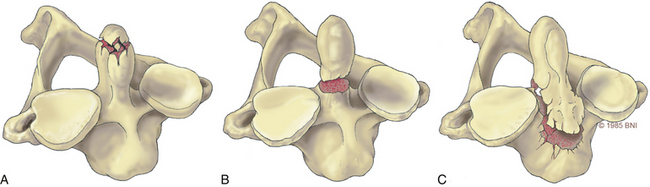
Odontoid fractures, a common injury of the cervical spine, are found in conjunction with almost 60% of atlas fractures and with 10% to 20% of all cervical fractures.4,5 Based on the Anderson and D’Alonzo nomenclature for odontoid fractures, almost 40% are type II fractures6 (Fig. 38- 1). Although conservative management should be considered, given the high rate of nonunion associated with these lesions, surgery is the gold standard of treatment. Historically, dorsal wiring techniques, such as C1-2 arthrodesis with halo-vest immobilization for 3 months, offered an excellent fusion rate (as high as 97%).7 The main shortcoming of wiring methods is the long-term loss of patient mobility from sacrifice of the atlantoaxial joint and prolonged halo-vest immobilization immediately after surgery.7 Odontoid screw fixation, introduced by Bohler8 and Nakanishi’s group,9 has eliminated the need for halo-vest immobilization, while preserving motion at C1-2: the fusion rate can be as high as 100% (92–100%),10 and it is one of the only motion-preservation stabilization procedures available in spine surgery.
Other key contraindications to this procedure include exclusion of patients with disruption of the transverse atlantal ligament as seen on MRI,11 osteopenia with poor bone quality, inability to reduce a displaced fracture, and the presence of a type II fracture that extends across the base of the odontoid in an oblique plane. A disrupted transverse atlantal ligament results in dorsal migration of the fusion fragment during screw insertion; it does not address rupture of the transverse ligament even if the fracture heals. The inability to reduce a fracture appropriately to restore alignment and an oblique fracture line make capture of the fractured dens challenging. Osteopenia is a key contraindication that can result in “windshield wiping” of the screw with the potential to cause neurologic injury.
In the case of a ventral dislocation, the patient is placed supine with the neck extended or hyperextended and in a three-pin holder or halo tongs if preoperative traction is necessary. In the case of a dorsal dislocation, the patient is placed in a military chin-tuck position under fluoroscopic guidance. At our institution, we use intraoperative stealth image guidance to visualize bony anatomy in the coronal plane, eliminating the need for two image intensifiers. In a patient with a large barrel chest, it is difficult to obtain the necessary sagittal trajectory for screw placement. This problem can be corrected by translating the head and neck ventrally by hyperextending the neck with direct visualization using lateral fluoroscopy (Fig. 38-2). A very large chest can make the procedures technically impossible.
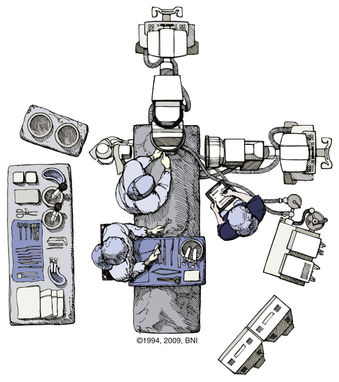
FIGURE 38-2 Positioning of two C-arm fluoroscopes for odontoid screw fixation.
(Used with permission from Barrow Neurological Institute.)
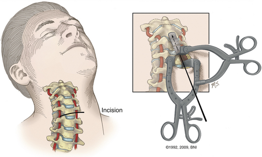
A transverse skin incision is made at the level of the cricothyroid junction, and the platysma is divided longitudinally to the ventral border of the sternocleidomastoid muscle. The dissection is performed using natural planes to the level of C4-5 (Fig. 38- 3). Blunt dissection proceeds rostrally to the level of the C2-3 disc space, and the retropharyngeal space is opened at C2. The medial borders of the longus colli muscles are coagulated and elevated laterally to maintain exposure. Next, it is important to expose the midline of the body of C2 because the midline keel of C2 is the landmark for screw placement. Doing so requires creating a midline trough through the anulus and disc at the C2-3 interspace. The placement of this entry site is critical because rostral placement of a screw can cause the shaft of the screw to lie too close to the overlying ventral cortex of C2. In this scenario the screw can cut out, or windshield-wipe out, of the C2 body, and pseudarthrosis can then develop.
More recently, image-guided navigation for placing odontoid screws has been employed. When this technique is used, the patient’s head is placed in a three-point fixation device and secured to the operating table. Using isocentric C-arm fluoroscopy, intraoperative images are obtained and 3D reconstruction is performed using the StealthStation (Medtronic, Minneapolis, MN). Using the coronal trajectory on the StealthStation, the midline of the C2 body is identified and a K-wire is advanced through the odontoid fracture. Real-time lateral fluoroscopy is used to monitor progress in the lateral plane until the K-wire approaches the cortex of the odontoid tip. Although the sagittal trajectory on the StealthStation may be used, it is not reliable. As force is applied on the C2 body during K-wire insertion, the body is pushed down and an error in sagittal trajectory is introduced, which can result in misplacement of the screw. As a result, we use image guidance for the coronal trajectory of the screw and lateral fluoroscopy for the sagittal trajectory and to monitor real-time progress of the K-wire and screw. Once the K-wire is placed, the bone can be drilled if it is very dense. The path is then tapped and a 4-mm screw is advanced under fluoroscopic guidance until it approaches the distal cortex of the dens. At this point, a cannulated titanium screw is selected (lag or fully threaded 4 mm). The screw is advanced and tightened until the screw head is just countersunk with respect to the body of C2 (Fig. 38-4). The screw length can be customized by measuring the K-wire depth on the fluoroscopic image.
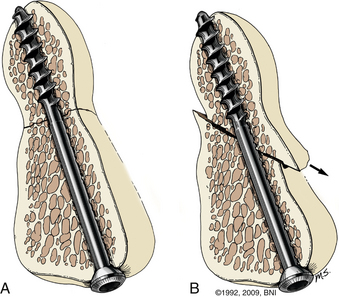
FIGURE 38-4 Ventral screw fixation of the odontoid with ideal (A) and suboptimal (B) screw placement.
(Used with permission from Barrow Neurological Institute.)
Hangman’s Fracture
Traumatic spondylolysis of the C2 isthmus, also known as hangman’s fracture, can be treated surgically or with an external orthosis, depending on the extent of dislocation and angulation. There are three types of hangman’s fractures, according to the classification devised by Effendi and modified by Levine and Edwards.12 In type 1 injuries there is a normal C2-3 intervertebral disc and less than 3-mm displacement without angulation. The mechanism of injury is hyperextension with axial loading, and the fracture can be treated in an external orthosis. Type 2 injuries consist of disruption of the C2-3 disc space and ventrally angulated or displaced fractures. The mechanism is combined hyperextension and axial loading followed by hyperflexion. This injury can be treated surgically or by placing the patient in an external orthosis. Type 3 injuries involve ventral displacement with hyperflexion of the axis associated with unilateral or bilateral facet dislocations. The mechanism of the dislocation is flexion and distraction, with hyperextension responsible for the spondylolisthesis. This injury is treated surgically.
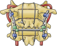
Direct reduction and fusion of a type 2 hangman’s fracture is possible by placing a screw through the pars and into the vertebral body. This cannot be performed in most cases given the size of the pars and the morphology of the fracture. If dorsal fusion of a hangman’s fracture is preferred, then screws are placed into the C1 and C3 lateral masses with the connecting rods as described in the section on dorsal upper cervical fixation. With a rib graft placed over the C1-3 dorsal arches, a multistranded titanium cable is passed under the rods and over the rib graft. With appropriate tensioning of the cable, the fractured C2 pars can be reduced, which enhances the fusion (Fig. 38-5).
Related posts:
 Definition and Assessment of Dysfunctional Segmental Motion
Pathophysiology of Cervical Myelopathy: Biomechanics and Deformative Stress
Combined Ventral-Dorsal Surgery
Bone Void Fillers: Bone and Bone Substitutes
Medical Management of Neck and Low Back Pain
Posterior and Transforaminal Lumbar Interbody Fusion
Definition and Assessment of Dysfunctional Segmental Motion
Pathophysiology of Cervical Myelopathy: Biomechanics and Deformative Stress
Combined Ventral-Dorsal Surgery
Bone Void Fillers: Bone and Bone Substitutes
Medical Management of Neck and Low Back Pain
Posterior and Transforaminal Lumbar Interbody Fusion
Stay updated, free articles. Join our Telegram channel

Full access? Get Clinical Tree


