Analog Signal Recording Principles
Charles M. Epstein
ANALOG AND DIGITAL RECORDING
Digital analysis and storage have transformed modern neurophysiology in ways that could only be imagined and envied by the founders of EEG. But the “front end” of all recording systems, the portion that interfaces with the patient, remains analog; and understanding the operation of analog components can also give insight into aspects of signal processing that are now performed mostly by digital techniques. Analog refers to methods of handling data that are physically similar to the original signal. For example, the moving pens and ink traces of the original electroencephalographs produced waveforms that mirrored the electrical potential differences on the scalp, and the wavy grooves of old-fashioned vinyl records follow the frequencies and amplitudes of the sound waves produced by stereo systems. Simple amplification of the microvolt potentials in EEG is an analog process. Analog data “looks like” the original signal, which the zeroes and ones of digital representations do not. Ideally, each type of data processing would produce a perfect reflection of the original waveforms. In practice, each is subject to its own limitations and potential for inaccuracy, which will be discussed in the following chapters. More detailed discussion of the material here can be found online in the Guidelines of the American Clinical Neurophysiology Society (1) and in those of the International Federation of Clinical Neurophysiology (2).
THE HOSTILE WORLD OF CLINICAL NEUROPHYSIOLOGY
Figure 6.1 shows the approximate amplitudes of electromyographic activity (EMG), EEG, and evoked potential signals in relation to the many sources of noise that constantly threaten to overwhelm them. This vast range of voltages requires the use of a logarithmic scale. So, for example, ECG recorded from the head can be a thousand times larger than a brainstem evoked potential. Within electrified buildings, the 50- or 60-Hz electric field on human bodies can be 10,000 times larger than the EEG. Some physiologic signals, such as EMG and the standing potential on the retina, can also represent noise in relation to smaller signals that we need to see behind them.
At first glance, it may seem impossible that any interpretable recording could be performed through noise that is orders of magnitude larger than the signal of interest. This chapter discusses some of the ubiquitous artifacts in Figure 6.1, the features of the analog front end that are designed to defeat them (while allowing faithful recording of the desired signal) and the ways in which they may nonetheless make an unwanted appearance in EEG and other neurophysiologic recordings. The major entry points and barriers to noise consist of the electrode interface, the amplifier inputs, and analog filters. The following sections describe from front to back the different components of the system and the features that contribute to accurate recording of neurophysiologic signals.
ELECTRODES
EEG and other recording electrodes provide an interface between lead wires, which conduct current as the flow of electrons and human tissues, which transmit it through the movement of ions. Because cutaneous oils and keratin are good insulators, placing dry metal electrodes directly on dry skin is usually ineffective. Keratin is often removed by rubbing the skin gently with mild abrasives, and sometimes oils are removed separately with alcohol wipes. (Despite such preparations, the epidermis remains the single greatest barrier to current flow between the body and the recording system.) In addition an ionic solution, or electrolyte, is placed between the skin surface and the electrode. As with human extracellular fluids, the most abundant ions in the electrolyte are sodium and chloride. The consistency of the electrolyte ranges from free-flowing solutions to thick sticky pastes. The latter are used to help hold cup electrodes mechanically against the scalp. The former are chosen when the cup is attached by other means and must be filled with electrolyte through a small hole in the middle.
Contact between the electrolyte and the electrode causes opposite charges to line up at the metal-ionic boundary. The simplest model for this arrangement is the “electrical double layer,” first proposed in the 1850s by Helmholtz. The double layer contributes to the stability of the interface and also represents a capacitance that augments the apparent current flow. At times, especially with new electrodes, the electrical double layer undergoes sudden, poorly understood transitions that produce electrode “pops” and a variety of bizarre oscillations.
The junction between the metal electrode and the ionic electrolyte also develops a half-cell potential, which reflects the electrical force of incipient chemical reactions between them. It also represents half of an electrical battery. The half-cell potential can be much smaller than that in a flashlight battery and still be enormously larger than the EEG. Ideally this would not be problem, because the half-cell potentials on any pair of matching electrodes would be identical, and thus would simply cancel out when those electrodes are connected to an amplifier.
However, half-cell potentials can be altered in a number of ways, including drying out of the electrolyte, its dilution by sweat or other fluids, relative differences in temperature, or exposure of different metallic surfaces by wear and tear. These potentials are also affected by movement of the electrode against the electrolyte and the skin, which disrupts the electrical double layer. The effect of movement is reduced by using cup-shaped electrodes, which hold a larger reservoir of moist electrolyte.
However, half-cell potentials can be altered in a number of ways, including drying out of the electrolyte, its dilution by sweat or other fluids, relative differences in temperature, or exposure of different metallic surfaces by wear and tear. These potentials are also affected by movement of the electrode against the electrolyte and the skin, which disrupts the electrical double layer. The effect of movement is reduced by using cup-shaped electrodes, which hold a larger reservoir of moist electrolyte.
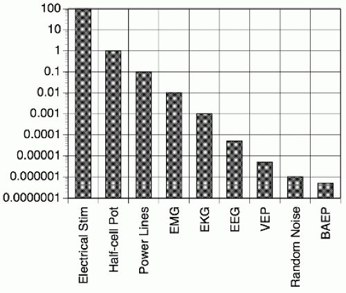 Figure 6.1 Potential sources of noise in neurophysiologic recording. Sources may represent noise in some contexts and signals in others. Note the logarithmic scale. |
Chemical interactions at the electrode surface consist of redox reactions, in which an electron is donated or removed from an ion. Since the product of such interactions is commonly a toxic species, such as hydroxyl ions or chlorine gas, care must be taken to avoid injury of the underlying tissues. The safest operating zone for recording and stimulating electrodes is one where they carry only a limited alternating or balanced pulse current, small enough to be transmitted entirely through the double-layer capacitance rather than through redox reactions. Passage of direct current through the double layer will more readily produce chemical changes at the metal surface, including electrical polarization, which impedes the free flow of current in one direction more than another, increases impedance at low frequencies, and may be associated with a substantial change in the half-cell potential.
Scalp and other cutaneous electrodes are usually made from gold—which is inert and therefore produces smaller half-cell potentials—or silver coated with a layer of silver chloride. Disposable stick-on electrodes almost always use a silver-silver chloride interface. Combined with a chloride electrolyte, the latter represents the most stable electrode available for neurophysiologic applications, resistant to polarization and with the best characteristics for low-frequency and direct-current recording. Occasionally the exposure of metallic silver to the light pulse from photic stimulators produces synchronous photoelectric discharges, which may be puzzling to novice interpreters.
Intracranial strip and depth electrodes are generally made from stainless steel or platinum. The more favorable electrical properties of platinum tend to be offset by its greater cost. With modern amplifiers the high impedance and polarization of stainless steel represent less of a problem than they did in the past.
LEAD WIRES, JACKBOX, AND CABLES
The lead wires, jackbox, and cables are basically passive components whose function is transparent. Excessive separation of the lead wires should be avoided. The capacitance of extremely long cables can attenuate very high frequencies. These effects can be ameliorated by placing the amplifiers inside the jackbox or even directly on the electrodes and by using fiberoptic connections to replace electrical cables. In exceptional circumstances, such as inside the bore of a high-field MRI system, resistors should be placed in series with every electrode lead to prevent induction of excessive current. When troubleshooting, it is worth remembering that if things mysteriously go wrong, the commonest culprit is a bad lead wire, cable, or connector.
ELEMENTARY ELECTRONICS
Classically the building blocks of the EEG front end are amplifiers, filters, switches, and potentiometers. The top portions of Figures 6.2, 6.3, 6.4, 6.5 and 6.6 sketch the simplified “transfer functions” of an amplifier, a voltage divider, a high filter (which, confusingly,
an engineer would call a low pass filter), and a low filter (LF) (which an engineer would call a high pass filter). The amplifier (Fig. 6.2) makes the desired signal larger. The purpose of the LF is to block frequencies so low that they carry more noise than signal, and thus are better removed. The high filter blocks frequencies so high that they carry more noise than signal. These simple functions remain the basic components of analog recording. For this discussion the amplifier will remain mostly a “black box,” which is the way electrical engineers prefer to use modern integrated circuits anyway. The voltage divider and filters are represented in the form of their simplest analog components: resistors and capacitors.
an engineer would call a low pass filter), and a low filter (LF) (which an engineer would call a high pass filter). The amplifier (Fig. 6.2) makes the desired signal larger. The purpose of the LF is to block frequencies so low that they carry more noise than signal, and thus are better removed. The high filter blocks frequencies so high that they carry more noise than signal. These simple functions remain the basic components of analog recording. For this discussion the amplifier will remain mostly a “black box,” which is the way electrical engineers prefer to use modern integrated circuits anyway. The voltage divider and filters are represented in the form of their simplest analog components: resistors and capacitors.
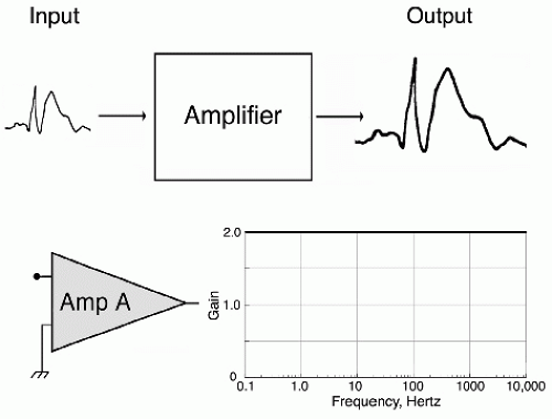 Figure 6.2 Amplifier. The top sketch shows the amplifier as just a “black box” that magnifies the size of the signal. At bottom left is the standard circuit symbol for an amplifier, with two inputs on the left and an output on the right. At bottom right is a graph of the output. It shows a straight line representing a gain of 2.0 at the top of the y-axis, because the gain is the same at all frequencies. This simple “single-ended” amplifier has asymmetric inputs: one terminal is “hot” and the other is usually connected to system ground (the bent trident symbol). The inherent asymmetry prevents accurate rejection of noise signals, even when they are equal at both inputs. |
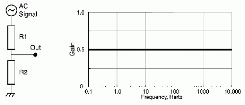 Figure 6.3 Resistance bridge. The circuit symbol for a resistor [R] is a cylinder. The two resistors here are labeled R1 and R2, and both have the same value. Current from the AC input signal at the top flows through the resistors to system ground (the bent trident symbol) at the bottom. The output voltage graph is a straight line with a gain of 0.5, because a pure resistive circuit has the same gain at all frequencies. |
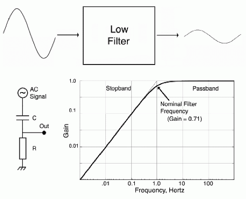 Figure 6.4 Low filter (LF). The low-frequency waveform coming out is smaller than the one going in. The circuit symbol for the capacitor (C) is a pair of parallel lines. Current from the AC input signal at the top flows through the capacitor and the resistor [R] to system ground at the bottom. The log-log output voltage graph shows a horizontal line indicating a gain of one on the right side, where frequencies are above the cutoff. Below the cutoff frequency, gain drops steadily as frequency increases. |
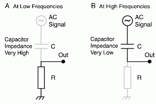 Figure 6.5 Sketch of how changing frequencies produce the LF behavior graphed in Figure 6.4. At low frequencies (A) the capacitor impedance becomes very high, so the capacitor and signal source practically drop out of the circuit. At high frequencies (B) the capacitor impedance becomes very low, and the resistor practically drops out of the circuit. |
Amplifiers (Fig. 6.2) have the primary purpose of magnifying the signal from a range measured in microvolts up to several volts, which can do something useful such as moving mechanical pens or undergoing analog-to-digital conversion to a stream of numbers. The ratio of the signal coming out of the amplifier to its size going in is called gain. For both analog and digital systems gain should be in the range of 100,000 or more. In neither case, however, is gain easily apparent from the system output. This is because the EEG signal is universally shown in terms of sensitivity, the ratio of microvolts to millimeters on a paper or electronic display.
Figure 6.3 shows a simple voltage divider or potentiometer in the form of a two-resistor network. A resistor is a circuit element with two characteristics: it partially blocks the flow of current according to Ohm’s law (voltage = current × resistance), and this relationship is independent of signal frequency. Potentiometers are useful when for any reason voltage must be reduced rather than increased (i.e., the gain should be less than one). The signal enters the two-resistor network as the AC voltage source at the top and passes through the resistors to system ground. According to Ohm’s law, if the resistors share the same current and have equal values, the voltage output at the middle of the network must be half the voltage at the top. Since the function of the resistors is the same at all frequencies, the graph shows a steady gain of 0.5 all the way across.
Related posts:
 Dynamics of EEGs as Signals of Neuronal Populations: Models and Theoretical Considerations
EEG of Degenerative Disorders of the Central Nervous System
Metabolic Disorders and EEG
Anticipating Seizures Based on EEG
Intracranial Monitoring: Depth, Subdural, and Foramen Ovale Electrodes
EEG Event-Related Desynchronization (ERD) and Event-Related Synchronization (ERS)
Dynamics of EEGs as Signals of Neuronal Populations: Models and Theoretical Considerations
EEG of Degenerative Disorders of the Central Nervous System
Metabolic Disorders and EEG
Anticipating Seizures Based on EEG
Intracranial Monitoring: Depth, Subdural, and Foramen Ovale Electrodes
EEG Event-Related Desynchronization (ERD) and Event-Related Synchronization (ERS)
Stay updated, free articles. Join our Telegram channel

Full access? Get Clinical Tree


