Computed Tomography
Daniel S. Chow
Angela Lignelli
INTRODUCTION
This chapter provides a framework for understanding the basic principles of x-ray (roentgenogram) production and computed tomography (CT) image formation along with appropriate window and level parameters for evaluation of intracranial pathologies. In addition, the common indications for CT are discussed along with precautions and recommendations related to CT usage and iodinated contrast. Advanced CT modalities including CT perfusion and CT angiogram are given special consideration.
DESCRIPTION
CT is based on image reconstruction from sets of quantitative x-ray measurements through the head. A beam of x-rays serves as the source of photon energy, which is received by a detector. Although the exact physics of x-ray production is beyond the scope of this chapter, this section will try to simplify the basic principles of x-ray production important for image formation. Briefly, x-ray beams are generated when electrons, produced in the cathode of the tube unit, strike the anode target. The potential difference across the tube is measured as peak kilovoltage (kVp). Thus, increasing the kVp increases the energy of x-rays produced, which will increase penetration of the beam during image production but decrease contrast (and vice versa). Imaging intravenous (IV) or oral contrast in CT imaging is based on the differential attenuation of the x-ray beam through various tissues. As the electron density of the tissue increases, the attenuation increases (giving a “whiter” image). Therefore, the bony calvarium appears “white” compared to soft tissue and air because of its greater attenuation.
Modern CT scanners use highly collimated x-ray beams, which are rotated over many different angles to obtain a differential absorption pattern across various rays through a slice of a patient’s body. A circular scanner gantry houses the x-ray source and detectors; the plane of the circle can be tilted to perform scans at a range of angles from axial to coronal, depending on head position and scanner specifications. The x-ray source rotates around the patient’s head, and the x-ray attenuation through the section plane is measured in compartments called voxels. A voxel is a volume element similar to a picture element, or pixel, with the added dimension of section thickness to create an image volume component. Through projection reconstruction, the computer creates or builds the image from more than 800,000 measurements per image plane and assigns a number to each voxel according to its x-ray attenuation (which is proportional to tissue electron density averaged over the volume of the voxel). These values are termed Hounsfield units (HU) (Table 20.1) in honor of Nobel Prize winner Sir Godfrey Hounsfield who first developed CT technology in 1973.
CT of the head differentiates cerebrospinal fluid (CSF) and brain as well as white matter and cortical gray matter, delineates the deep gray nuclei from the internal capsule, and images the skull and skull base in detail. Noncontrast computed tomography (NCCT) of the brain is especially useful for identifying acute hemorrhage, which is easily and reliably visualized as higher density than normal brain or CSF. Typically, intracranial arteries are not well delineated on standard NCCT. Iodinated water-soluble contrast agents, which have high x-ray density, when administered intravenously enhance differences in tissue density, demonstrate vasculature and vascular pathology, and detect areas of blood-brain barrier breakdown.
A major limitation of CT has been imaging the posterior fossa, where linear artifacts appear because bone selectively attenuates the low-energy components of the x-ray beam; the resulting “beam hardening” creates dense or lucent streaks that project across the brain stem and may obscure underlying lesions in the brain stem and cerebellum. However, new detector technology and image-processing algorithms have reduced this artifact in the latest CT scanners, improved spatial resolution, and reduced the radiation dose. Current CT technology allows scan time per section (“slice”) to be shortened to less than 1 second to minimize motion artifact. Multisection helical CT can acquire contiguous thin sections to produce three-dimensional (3D) data sets of an entire body part, such as the neck or head. Rapidly, repeated acquisitions can be used to acquire dynamic computed tomography angiography (CTA) and computed tomography perfusion (CTP) studies, which will be discussed later in this chapter.
TABLE 20.1 Hounsfield Units for Common Structures | ||||||||||||||||||||||
|---|---|---|---|---|---|---|---|---|---|---|---|---|---|---|---|---|---|---|---|---|---|---|
| ||||||||||||||||||||||
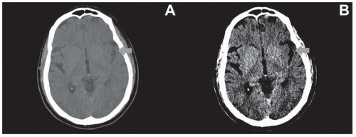 FIGURE 20.1 NCCT of the head with standard brain (A) and narrow stroke (B) windows in a patient with acute right-sided weakness. Stroke windows reveal loss at the left insular ribbon (arrow), which was not clearly visualized on conventional windows. |
WINDOWS AND LEVELS
Although CT imaging can display 4,096 shades of gray, the human eye can only visualize between 16 and 32 shades of gray, which is well beyond human perception. “Windowing” allows users to narrow the range of shades of gray, which in turn adjusts the contrast scale. Two factors that can be adjusted by the user are the window width (W) and the window level (L). The W determines the range of shades of gray that can be displayed. Therefore, “narrowing the window” would increase the contrast of the image. The L determines the center of the W. By convention, users can decrease the W by dragging the mouse from right to left, increasing the contrast. The L can be decreased by dragging the mouse from top to down on monitors.
Although the default “brain window” (80 W 40 L) is suitable for assessing a wide range of pathologies, there are several other important windows for neuroimaging to assess for subtle abnormalities. For example, evaluation of parenchymal hypodensity as a marker for early infarct in stroke patients may be improved by using narrow windows (35 W 35 L) (Fig. 20.1). Additionally, subdural hemorrhages are often located at the convexities adjacent to bone and may be difficult to identify due to beam hardening and volume averaging. Using wider windows may assist in countering these limitations (Fig. 20.2). Lastly, bone windows (2,000 W 200 L) are formed with wide ranges and centered above soft tissues and are best for evaluating for subtle nondisplaced calvarial fractures (Fig. 20.3).
Related posts:


Stay updated, free articles. Join our Telegram channel

Full access? Get Clinical Tree


