22

Endoscopic Pedicle Screw Instrumentation and Decompression
KEE D. KIM AND MARK W. HAWK

Standard posterolateral lumbar fusion requires extensive myoligamentous dissection and retraction. The paraspinal muscle injury associated with open surgery is often grossly visible by the ischemic discoloration of the paraspinal musculature after a lengthy procedure.1–6 Histologic findings include denervation and reinnervation changes that lead to early aging of the musculature.1–6 In addition, the postoperative pain and blood loss involved with open lumbar fusion are often significant.
Atavi endoscopic instrumentation developed by Endius (Plainville, MA) allows the surgeon to perform up to a two-level posterolateral spinal fusion with limited myoligamentous disruption and muscle retraction. Instead of a midline incision with extensive lateral dissection, a more direct approach along the plane of the pedicle is used via bilateral paramedian incisions.7 With less myoligamentous dissection, intraoperative blood loss and muscle injury are reduced. With the use of a patented flexible tubular retractor system, retraction injury to the surrounding musculature is minimized. Our preliminary study indicates that the intramuscular pressure adjacent to the tubular retractor is ~30 to 40 torr less than that with the use of a standard rigid retractor. If necessary, decompression may be performed through the same tubular retractor, and the ability to deliver an interbody fusion device endoscopically in the near future should make this system even more versatile.
In this chapter, we describe the Atavi endoscopic system and the surgical technique used to achieve the same posterolateral fusion as the standard open technique, but with a much smaller incision. The Atavi endoscopic lumbar decompression technique is also briefly described. It is important to emphasize that the technique given here is familiar to spine surgeons, with the exception of the Atavi endoscopic instrumentation, which is designed for use through a small working port.
Indications
Indications for endoscopic posterolateral fusion are similar to the standard open technique, with the exception that endoscopic fusion is limited to one or two levels. Some of the current indications include the following:
- Degenerative disk disease
- Grade I spondylolisthesis
- Supplementation of anterior lumbar interbody fusion
- Pseudoarthrosis from anterior stand-alone lumbar interbody fusion
- Lumbar spinal stenosis requiring fusion after decompression
When initially attempting the endoscopic technique, patients who have had previous surgery at the same level should be avoided. The anatomic landmarks seen through an endoscopic procedure are more limited compared with those visualized in open procedures. Patients with previous microdiskectomy and limited laminectomy, however, do not pose a special challenge. Any posterolateral fusion that may be difficult with an open technique (e.g., grade II or higher spondylolisthesis) should not be attempted until sufficient endoscopic fusion experience is achieved with more simple cases.
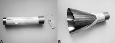
FIGURE 22–1 Smaller FlexPosure (maximum diameter of 40 mm) before (A) and after (B) deployment.
Surgical Equipment/Instrumentation
As in any endoscopic procedure, the Atavi instrumentation allows the surgeon to establish access, provide visualization, and perform surgery through an endoport.
Establish Access
- Guidewire and series of dilators: Five to 20 mm diameter dilators in 5 mm increments are available.
- FlexPosure endoretractor (Fig. 22–1): The FlexPosure is a 24 mm diameter cylindrical tube with a pivot in the center. When deployed, the distal part of the tube opens in a conical fashion to a maximum diameter of 40 or 63 mm, depending on whether or not the small or large FlexPosure is used. In general, the smaller-sized FlexPosure is adequate for a single-level fusion and decompression.
- FlexPosure spreader: The spreader is used initially to open the distal skirt of the FlexPosure. Because the FlexPosure is not rigid, the skirt may close partially during the procedure. During the surgical procedure, the spreader is then used to expand or redirect the skirt.
Provide Visualization
- Vacuum-controlled FlexArm (Fig. 22–2): This mechanical arm with multiple articulating joints is mounted to the operating table. It holds the FlexPosure endoretractor, scope, and camera in a steady position for surgery.
- Camera, light guide, and 30-degree scope: A bright light source with a three-chip camera provides a clear and crisp picture on the video monitor.
- Video monitor
- Standard fluoroscopy
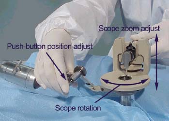
FIGURE 22–2 FlexArm with camera, light guide, and scope attachment.
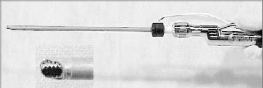
FIGURE 22–3 Microdebrider system with bipolar sheath and side port suction.
Perform Surgery
- Microdebrider system (MDS) with bipolar coagulator (Fig. 22–3): This single instrument allows the surgeon to debride and coagulate without changing to another instrument.
- Suction/irrigator: This suction instrument has an additional lumen connected to a sterile saline bag to provide irrigation. Blood and smoke may be suctioned, and the surgical field may be irrigated to provide adequate visualization.
- Endo instruments: The Atavi instrumentation tray has all the standard instruments necessary for posterolateral fusion adapted for use through an endoscopic port. A separate tray with a variety of curettes and rongeurs may be requested if decompression is planned.
- Implants: Top-loading polyaxial self-tapping pedicle screw/rod implants (TiTLE system, Endius) are available in a variety of sizes. Screw/plate implants (TriFix system, Endius) are also available for singlelevel fusions.
Operative Setup/Patient Positioning
Request one of the larger operating rooms because more equipment is required in endoscopic cases. A careful operative setup prior to skin incision will decrease mistakes and improve efficiency throughout the case.
The patient is placed prone on a radiolucent operating table, with the anesthesia equipment at the head of the table. The C-arm is placed caudad to the arm boards and cephalad to the surgeon. Positioning the endoscopic video tower at the foot of the bed will allow the surgeon and the assistant to perform the surgery without having to turn in an awkward position. For the same reason, the fluoro video monitor should be stationed across from the surgeon or at the foot of the table. The MDS and electrosurgical generators are placed in an unobtrusive location.
Surgical Technique
Determine Incision Site
- Check the patient to ensure that the trunk is not rotated or unevenly positioned on the table.
- Mark the midline using the anteroposterior fluoroscopic view.
- Delineate the cephalocaudad line of the incision by using an AP Ferguson view to mark the transverse lines through the middle of the superior and inferior pedicles of interest on each side.
- Determine the paramedian line of incision by using oblique views to mark vertical lines over the middle of the pedicles of interest. Oblique angles are set to look down the barrel of the pedicle and may vary from 10 to 25 degrees, depending on the level to be fused. The angle may also be estimated from preoperative CT or MRI.
- Mark bilateral vertical skin incision lines to be used over the previously marked paramedian lines. The lines should extend 1.25 to 1.5 inches (3.20 to 3.85 cm) in length, depending on whether one- or two level fusion is to be performed. They should also be centered between the horizontal cephalocaudad lines previously drawn. For the purpose of illustration, an L4 to S1 posterolateral fusion will be described.
Sequentially Dilate Soft Tissue
- Mount the FlexPosure retractor arm to the side of the bed.
- Prep and drape the patient.
- Make an incision over the marked vertical paramedian line. Extend the incision through the lumbodorsal fascia.
- Place an index finger through the lumbodorsal fascia, and palpate the bony landmarks. Medially angle the index finger and feel the transverse process, sacral ala, and facet joint.
- Position a dilator over the L5 transverse process and lateral to the pars interarticularis.
- Confirm proper position with AP Ferguson and lateral fluoroscopic views.
- After the first dilator is placed, place the next size dilator and remove the first. Repeat this process until the largest dilator has been placed. With the distal end of the dilator, gently scrape the soft tissue over the transverse process, sacral ala, and facet joint to expand the working space circumferentially.
Position FlexPosure
- Place the FlexPosure over the largest dilator, with the deployment string facing medially.
- Reconfirm the proper position of the FlexPosure using AP and lateral fluoroscopic views. On the AP view, the FlexPosure should be over the transverse process and pars interarticularis of L5; on the lateral view, it should be directly in line with the L5 pedicle and above the transverse process.
- Remove all dilators.
- Pull the FlexPosure deployment string upward while pushing FlexPosure against the bony surface to minimize the amount of soft tissue creeping under the skirt. Pulling the deployment string separates the distal cover of the FlexPosure to allow the skirt of the FlexPosure to open.
- Insert the FlexPosure expander all the way down to the stop tabs, and maximally expand the skirt.
- Gently rock the FlexPosure until the cephalad aspect of the FlexPosure skirt is above the L4 transverse process and the caudal aspect of the FlexPosure is over the sacral ala.
Secure FlexPosure
- Slide the saucer-shaped mount clamp over the Flex-Posure.
- Attach the scope retractor mount assembly to the distal end of the FlexArm.
- Dock the scope retractor mount assembly to the mount clamp. A vacuum-release button is used to move the mechanical arm so that the FlexArm holds the FlexPosure in a secure position.
Establish Visualization
- Slide the camera, light guide, and scope assembly into the scope retractor mount (Fig. 22–4).
- Ratchet the scope assembly laterally so that the 30-degree scope is pointing medially.
- Use a probe to correlate superior, inferior, lateral, and medial aspects of the surgical field with the view seen on the video monitor.
Prepare Surgical Site
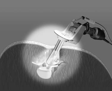
FIGURE 22–4 FlexArm securely holds FlexPosure and scope mount, allowing the surgeon free use of both hands.
Placement of Pedicle Screws
- Use a high-speed drill to clear the space around the entry point for the pedicle screw head.
- Place an awl at the entry point of the L4 or S1 pedicle. Use AP and lateral fluoroscopic views to adjust the position of the awl (Fig. 22–5).
- Gently tunnel the pilot hole down the pedicle with the pedicle probe. Verify with fluoroscopic views, and sound the pedicle wall to ensure that it has not been violated.
- Tap the pilot hole, and place the pedicle screw.
- Repeat the steps for other levels. Place the L5 pedicle screw last and in line with L4 and S1 screws to allow easier placement of the rod. Screw heads at L4 and S1 are anchor points to prevent the FlexPosure skirt from closing.
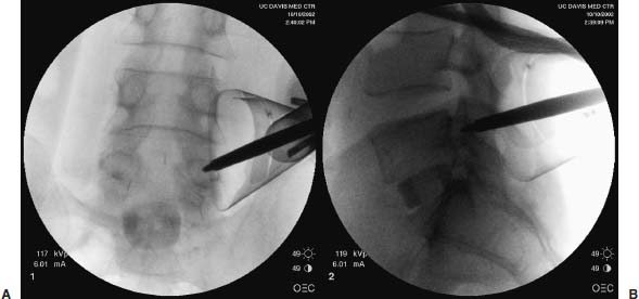
FIGURE 22–5 Anteroposterior (A) and lateral (B) fluoroscopic views confirm that the tip of the awl is in the pedicle and in good position. FlexPosure used in this case has a 40 mm maximum diameter.
Assemble the Construct
- Align the tulip head of the pedicle screws with an endoCobb dissector. The tulip head of the pedicle screws allows for several degrees of freedom and facilitates rod placement.
- Slide the appropriate-length rod over the tulip head of the screws. A rod holder may be used to adjust the position of the rod. If a curved rod is chosen, use a marking pen to distinguish the lordotic side.
- After the Marksman guide is snugly positioned over the L5 screw tulip head, insert and hand-tighten the cap screw. Use a torque wrench for final tightening while using the Marksman guide to provide countertorque. In two-level fusions, the middle pedicle screw is secured to the rod first.
- The cephalad and caudad screw caps are similarly placed and tightened. If compression or distraction is desired, an endoscopic compressor/distractor may be used. This instrument maintains a compression or distraction force while the loose cap screw is being tightened. For mild reduction of spondylolisthesis, the Spondy reduction driver may be used to pull a pedicle screw toward the rod before the pedicle screw nut screw is tightened.
Bone Graft Placement and Wound Closure
- Pack bone graft over the fusion surface.
- Obtain final hemostasis, and remove the FlexPosure by turning in a clockwise fashion. The muscle and fascia will close over the space previously occupied by the FlexPosure.
- Close fascia and skin in a standard manner. Because of the small size of the incision, this step takes only a couple of minutes.
Lumbar Decompression
If decompression is desired in addition to the posterolateral fusion, the same steps are taken, except that the endoscopic decompression is performed before the pedicle screws are placed.
- Place pedicle markers after the pilot holes for the pedicle screws are prepared. They serve as useful landmarks and are less obtrusive than the pedicle screws.
- Direct the FlexPosure skirt medially against the spinous process (Fig. 22–6). This may be aided by using the spreader to open the skirt in a mediolateral direction.
- Debride and coagulate the soft tissue over the facet and lamina with the MDS to expose the bony surface to be resected. An AP fluoroscopic view may be helpful in confirming the correct site prior to decompression.
- Thin down the bony surface, and delineate the border to be decompressed with a high-speed drill. Because an instrumented posterolateral fusion will be performed, aggressive bony resection including facetectomy may be performed.
- Detach the ligamentum flavum of the cephalad lamina and perform a laminotomy with Kerrison rongeurs. A ligamentum flavum elevator, chisel, and different Kerrison rongeurs are available for use.
- Confirm that adequate decompression is achieved using a Woodsen elevator and, if necessary, with AP/lateral fluoroscopic views.
- Redirect the FlexPosure laterally to remove pedicle markers and place pedicle screws.
- Complete the rest of the procedure as described previously.
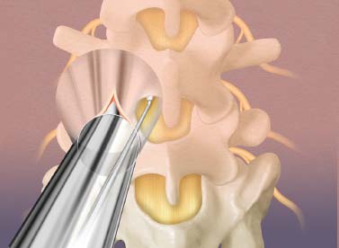
FIGURE 22–6 Palpate, dissect, and confirm with an instrument prior to bony resection. Limited depth perception requires careful use of instruments during decompression.
Complications and Avoidance
- Although the three-chip camera gives an excellent view of the surgical site, it does not provide a three-dimensional perspective; therefore, in portions of the surgery that require good depth perception, viewing directly down the FlexPosure may be necessary.
- Bleeding: Dissect very gently until the FlexPosure with the scope mount is positioned. If bleeding occurs before visualization is established, hemostasis will be difficult to achieve.
- Nerve root injury: A sharp instrument placed deep to the intertransverse ligament may damage the nerve root. Instead of using a guidewire that may inadvertently penetrate and injure a nerve root, use the 5 or 10 mm dilator to establish initial access.
- Pedicle screw misplacement: Always confirm with fluoroscopic views if there is any question about the position of the awl/probe/tap or pedicle screws.
- Durotomy: Dissect to define and visualize the thecal sac better prior to using a Kerrison rongeur to avoid inadvertent durotomy. If a durotomy with a CSF leak occurs, converting to an open procedure may be the only way to achieve a watertight dural closure. Another, less preferred, option is to cover the defect with Surgicel, followed by fibrin glue. To decrease the chance of developing a pseudomeningocele, a lumbar intrathecal drain may be placed just cephalad to the site of the leak.
Illustrative Cases
Case 1. Spondylolisthesis with Foraminal Stenosis
A 65-year-old woman presented with low back and left leg pain lasting for more than 10 years. Her pain was refractory to repeated nonsurgical therapy and was compromising her activities of daily living. Preoperative lumbar plain films and MRI showed grade I L4–L5 degenerative spondylolisthesis with foraminal stenosis (Fig. 22–7). The patient underwent an L4–L5 anterior interbody arthrodesis with femoral ring allograft, followed by endoscopic L4-L5 posterior instrumentation and left L4–L5 foraminotomy (Fig. 22–8). She had good relief of low back and left leg pain postoperatively.
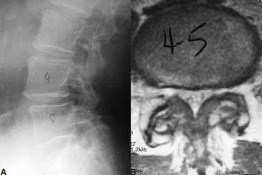
FIGURE 22–7 Lumbar lateral x-ray (A) and axial T2-weighted MRI (B) at the level of L4–L5 disk.
Case 2. Degenerative Disk Disease
A 56-year-old woman reported the severity of her chronic low back and bilateral leg pain to be 10 out of 10 on the visual analogue scale. On lumbar plain films and MRI, she had mild degenerative changes at L4–L5 and L5–S1. Because her pain was not getting better with analgesics, epidural steroid injections, and physical therapy, lumbar diskogram was performed. She had a positive diskogram at L4–L5 and L5-S1, reproducing her baseline symptoms. The patient underwent L4–L5 and L5–S1 anterior lumbar arthrodesis with femoral ring allograft supplemented with posterior endoscopic instrumented fusion (Fig. 22–9). She reported more pain postoperatively from the abdominal incision than the lumbar incisions (Fig. 22–10). She had near complete relief of her preoperative symptoms 1 month after surgery.
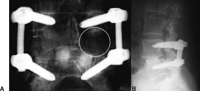
FIGURE 22–8 Anteroposterior (A) and lateral (B) postoperative x-ray. Although not easily visualized (the area within the circle), the left L4‒L5 decompression is demarcated on the AP x-ray by its lucency compared with the right side.
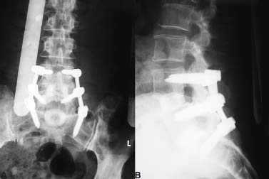
FIGURE 22–9 Immediate postoperative anteroposterior (A) and lateral (B) x-ray.
Acknowledgment
We would like to thank Dorie DeCosta and Bruce Dilts for assisting with the manuscript and Endius for providing some of the illustrations.
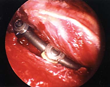
FIGURE 22–10 Intraoperative endoscopic view as the FlexPosure is being removed. Note the lack of ischemic discoloration involving the paraspinal musculature commonly encountered with open cases.
REFERENCES


