CHAPTER 376 Endovascular Stenting of Intracranial Aneurysms
Overview: Conceptual Evolution and History of Intracranial Stenting for Aneurysms
The impetus for stent-supported aneurysm embolization was the recognition that many wide-necked aneurysms were not amenable to endovascular treatment simply because embolization coils could not be reliably retained within the aneurysm fundus. Although many of these lesions could be successfully treated using a balloon-remodeling technique,1,2 this approach was perceived to be technically demanding, risky, and without an adequate “bail-out” strategy should the coils begin to prolapse into the parent artery during treatment. Intracranial stenting can overcome many of these limitations. These devices can be placed into the parent arteries to provide a durable mesh barrier across the aneurysm neck, which prevents coils from prolapsing out of the aneurysm after detachment.
Initial Applications of Stents for Aneurysm Therapy
In the early 1990s, the neuroendovascular group at the State University of New York at Buffalo described the application of stents to treat experimental aneurysms. The conclusions drawn from their initial set of experiments delineated the basic principles underlying stent-supported aneurysm therapy and essentially predicted the emergence of adjunctive intracranial stenting for aneurysms that would occur during the next decade.

FIGURE 376-1 Schematic of stent placement for parent artery protection. The wide-necked side wall aneurysm (A) is difficult to treat with coil embolization in the absence of adjunctive techniques. The aneurysm neck depicted is nearly as wide as the largest dimension of the aneurysm fundus. If coils are introduced in the absence of an adjunctive device to protect the parent artery (e.g., either a balloon or a stent), the coils will typically herniate (B) into the parent artery. A permanently implanted stent (C) provides durable parent artery protection, with the struts of the stent extending across the aneurysm neck and preventing the herniation of coils into the parent artery.

FIGURE 376-2 Schematic of stent placement achieving flow diversion. Aneurysms often occur at points of vessel angulation (A), setting up an inflow jet into the aneurysm fundus (arrow), with flow-induced shear forces along the dome, and exiting through an outflow zone located inferiorly. Stent placement theoretically may improve the hemodynamics by straightening the angulation of the vessel (B) to direct the dominant flow jet into the native basilar artery (large arrow) rather than the aneurysm and the struts of the stent disrupting the flow jet into the aneurysm (smaller arrows).

FIGURE 376-3 Schematic of stent placement achieving parent vessel remodeling. The wide-necked side-wall aneurysm (A) may be treated by trans-stent coiling (B). In addition to retaining the coils within the aneurysm, the stent may provide a scaffolding and stimulus for endothelial and neointimal overgrowth in the weeks to months after implantation (C). Over this time, the tissue extending over the aneurysm neck–parent artery complex (C, enlargement) may provide an additional barrier between the parent artery and aneurysm, functioning to prevent aneurysm recanalization.
Early Experience with Balloon-Expandable Stents
Several years later, Higashida and associates6 described the first successful transstent coiling of a circumferential, fusiform basilar artery aneurysm that could not be coiled using conventional techniques. During the ensuing 5 years, several additional case reports and small case series appeared in the literature describing the off-label applications of balloon-mounted coronary stents (BMCSs) to support the coiling of wide-necked intracranial aneurysms.7–13 During this initial era, stent-supported aneurysm treatment was greatly limited by the rigid nature of the available balloon-expandable coronary stents and the subsequent challenges involved with the delivery and deployment of these devices within the tortuous cerebrovasculature.
Self-Expanding Intracranial Microstents
In 2003, Neuroform (Boston Scientific, Fremont, CA), the first intracranial, microcatheter-delivered, self-expanding nitinol microstent was released in the United States for use in treating wide-necked aneurysms under a Humanitarian Device Exemption. Neuroform and its delivery system are far more flexible than the predicated BMCSs. These characteristics greatly facilitated delivery and deployment within tortuous segments of the cerebrovasculature.14 In 2007, Enterprise (Cordis Neurovascular/Johnson and Johnson, Warren, NJ) was introduced in the United States, providing a second self-expanding intracranial microstent (SEIM) for the treatment of intracranial aneurysms. The Enterprise stent presents several benefits over Neuroform, including ability to be reconstrained, a lower-profile delivery system, and a technically less-complicated deployment mechanism. The introduction of these devices led to a marked increase in the number of stent-assisted aneurysm treatments performed and greatly broadened the scope of lesions amenable to endovascular therapy. As practitioners gained experience with SEIMs, novel approaches to more complex lesions were innovated and the sophistication of endovascular reconstruction increased.15–22 During the past decade, stenting has become a standard adjunctive technique used to facilitate the treatment of wide-necked and complex aneurysms.
Parent Vessel Remodeling
In addition to their ability to provide durable parent vessel protection, stents have several possible effects on the physiology and biology of the aneurysm–parent vessel complex that could conceivably affect the durability of endovascular aneurysm treatment:
Experimental and Histopathologic Evidence
Given the relative flexibility and low metal surface area coverage (e.g., Neuroform, 6% to 9.5%) of the commercially available SEIMs, the ability of these devices to produce “physiologically significant” parent vessel remodeling could be questioned. Canton and associates23,24 performed a series of experiments to assess the impact of the Neuroform stent on intra-aneurysmal flow. These authors demonstrated that two stents placed in a Y configuration reduced the velocity of the inflow jet by 11% and reduced residual intra-aneurysmal vorticity and shear stress by more than 40%. With respect to biologic remodeling, only a single case is available in the literature describing the histopathologic appearance of an implanted Neuroform stent at autopsy.25 The aneurysm in this case was treated solely by stenting because subsequent attempts to place coils were unsuccessful. After this patient died of unrelated causes 4 months later, an evaluation of the explanted aneurysm demonstrated de novo fibroelastic tissue growing across the aneurysm neck and moderate intimal thickening along the stented segment of the parent vessel.
Clinical Evidence
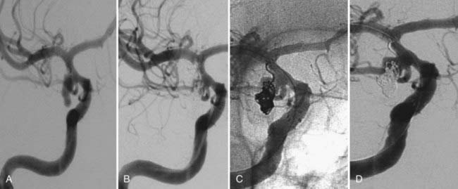
The available data from clinical case series have provided some additional, albeit preliminary, evidence that stenting may improve the durability of endovascular aneurysm therapy. Aneurysms treated with stents are wide necked, typically larger, and often in a terminal location. These characteristics would predict a very high rate of recurrence with standard coiling techniques. Evaluation of mid- and long-term follow-up results from the collaborative Barrow Neurological Institute–Cleveland Clinic database demonstrated a surprising level of long-term durability in aneurysms treated with stent-support.14,26,26a At an average follow-up of 12.9 months, 72% of aneurysms demonstrated either stability or progressive thrombosis (Fig. 376-4). Of the 28% aneurysms that demonstrated recanalization, defined as any amount of increased filling in comparison to the immediate postcoiling result, many were either very large or giant aneurysms. Small (<10 mm) aneurysms actually recanalized at a very low rate (9.3%), with only 3.1% requiring retreatment.

FIGURE 376-4 Progressive thrombosis after stent-supported coiling. Native (A) and subtracted (B) images in the working angle for the stent-supported coil embolization of a previously ruptured and partially clipped residual carotid-ophthalmic aneurysm. During the introduction of coils, the microcatheter was pushed out of the aneurysm. Attempts to traverse the stent and recatheterize the aneurysm resulted in some movement of the recently implanted stent. As such, no further embolization was performed despite the significant filling of the entire residual aneurysm (B) throughout the loosely packed coil mass. It was elected to allow the stent to endothelialize and become more stable within the vessel and to reattempt coiling in 12 weeks. Follow-up angiography at 12 weeks (C) demonstrates progressive thrombosis of the aneurysm in the interim to complete occlusion.
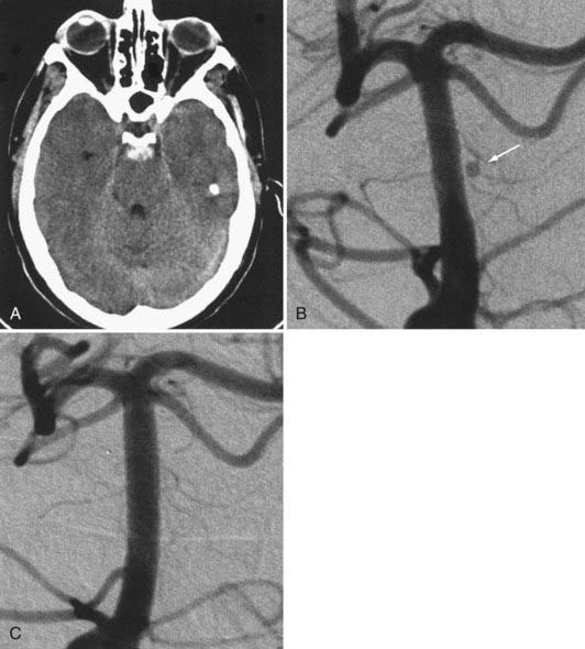
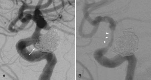
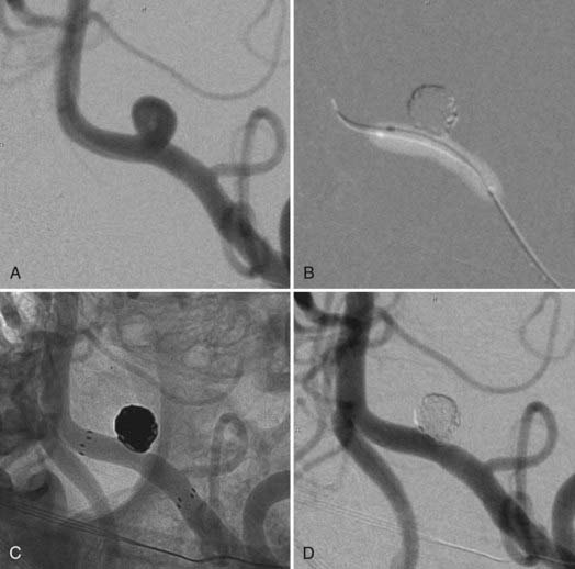
Several investigators have reported success with stents alone for the treatment of small dissecting and blood blister–like aneurysms, providing additional evidence in support of “physiologically significant” stent-induced remodeling of the parent vessel–aneurysm complex after self-expanding stent implantation.27–33 In the largest series, 10 patients with these types of aneurysms were treated with the Neuroform.29 Nine patients demonstrated interval regression or complete resolution after stent monotherapy (Fig. 376-5), and one was stable after only 1 month of follow-up. No patient experienced aneurysm rerupture during the follow-up period.

FIGURE 376-5 Stent monotherapy for the treatment of an uncoilable, unclippable midbasilar pseudoaneurysm. A, A 46-year-old man with subarachnoid hemorrhage on computed tomography scan. The initial angiogram was interpreted as normal; however, in retrospect, there may be a tiny bleb arising in the region of a midbasilar perforator. B, Six-week follow-up angiogram demonstrated interval growth of a midbasilar trunk aneurysm that measured slightly less than 2 mm. The lesion was too small to accept an embolization coil. Two telescoping neuroform stents (Boston Scientific, Fremont, CA) were placed. C, Follow-up angiogram 14 months after treatment showed complete occlusion of the aneurysm with maintained patency of the adjacent perforator vessels.
(From Fiorella D, Kelly ME, Turner RD, Lylyk P. Endovascular treatment of cerebral aneurysms. Endovasc Today. 2008; June:53-65.)
The observation of in-stent stenosis (ISS) (Fig. 376-6) in about 5% of patients after Neuroform placement (either as the sole or an adjunctive therapy) further suggests that these devices have the capability to stimulate a significant biologic response after implantation.34 Although the nature of the material accounting for the stenosis observed in these patients remains unknown, the angiographic appearance and time of onset are compatible with the intimal hyperplasia that has been encountered in other vascular beds after stenting for atherostenosis.34

FIGURE 376-6 In-stent stenosis after stent supported coil embolization. A 69-year-old woman with a large, wide-necked, unruptured aneurysm of the posterior wall of the internal carotid artery. A, Conventional angiography following the initial stent-supported embolization demonstrates residual filling along the entire aneurysm neck and into the aneurysm fundus inferiorly (arrow). B, Follow-up angiography performed at 9.5 months demonstrates diffuse in-stent stenosis (arrows). The aneurysm had progressed to complete occlusion in the interval. The patient was symptomatic, with transient ischemic attacks referable to the ipsilateral hemisphere that resolved immediately after the reinstitution of dual antiplatelet therapy.
Changes in the Application of the Self-Expanding Microstents
These observations have led to an evolution in the technical and theoretical application of intracranial stents. Self-expanding microstents have begun to be viewed not only as adjunctive devices to support coiling but also as tools that could potentially support the long-term durability of coil embolization—particularly in difficult cases that are prone to recurrence.
Procedural complications encountered by operators performing aneurysm coiling through in situ stents caused some to begin aneurysm coiling using a balloon-assist technique with stent deployment performed afterward—not only to stabilize the coil mass within the aneurysm but also in an attempt to remodel the parent vessel and thereby improve the long-term durability of the initial treatment. This technique avoids displacement or damage of the stent that can be inadvertently created during the manipulation of a microcatheter either into the stented segment of the parent vessel or through the stent tines and into the aneurysm.
High Metal Surface Area Stents (Flow Diverters)
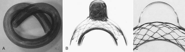
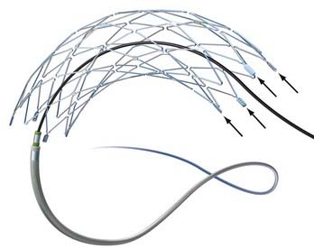
The concept of parent vessel reconstruction is quickly advancing with the recent development of dedicated flow-diverting endovascular constructs designed for intracranial use. These devices primarily target parent vessel reconstruction, rather than endosaccular occlusion, as the means by which to achieve definitive aneurysm treatment. Currently, these flow-diverting devices are high metal surface area coverage, stent-like constructs (Fig. 376-7) that are designed to provide enough flow redirection and endovascular remodeling to induce aneurysm thrombosis without the use of additional endosaccular occlusive devices (i.e., coils). At the same time, the pore size of the constructs is large enough to allow for the continued perfusion of branch vessels and perforators arising from the reconstructed segment of the parent vessel.35

FIGURE 376-7 Flow-diverting stent-like devices: construction and difference from other self-expanding intracranial microstents. A, The Pipeline embolization device (PED; Chestnut Medical, Menlo Park, CA) is a flexible, microcatheter-delivered, self-expanding, endovascular construct engineered specifically for the treatment of cerebral aneurysms. The device is composed of a braid of individual microfilaments. When fully deployed, the PED provides about 30% metal surface coverage at nominal expansion—a much higher percentage of coverage than that provided by conventional (noncovered) intravascular stents. The Neuroform (Boston Scientific, Fremont, CA) (B) and Enterprise (Cordis Neurovascular/Johnson and Johnson, Warren, NJ) (C) stents are self-expanding nitinol, microcatheter-delivered microstents. These stents are cut from a nitinol hypotube. When fully deployed, they provide between 6.5% and 9.0% metal surface area coverage
(From Fiorella D, Kelly ME, Turner RD, Lylyk P. Endovascular treatment of cerebral aneurysms. Endovascular Today. 2008; June:53-65.)
Summary: Evolution of Stenting Technology
The remarkable evolution of intracranial stents for aneurysm treatment has dramatically increased the number and type of lesions amenable to endovascular therapy. These devices not only facilitate the treatment of complex lesions but also have the potential to augment the durability of traditional endosaccular aneurysm occlusion. At some point in the future, stand-alone flow-diverting constructs may provide a definitive means by which to achieve a durable cure of selected aneurysms, completely obviating the need for endosaccular implants in these cases.
Commercially Available Devices
Balloon-Expandable Stents
Device Delivery and Deployment
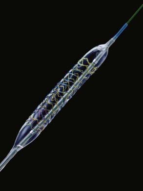
The BMCSs consist of an angioplasty balloon catheter on which a collapsed (but expandable) cylindrical metal cage is mounted. The balloon catheter on which the device is mounted may either be designed for over-the-wire delivery, whereby the microwire exits the proximal hub of the delivery catheter, or monorail delivery, whereby the microwire exits the side wall of the distal aspect of the catheter. Over-the-wire delivery allows for the transmission of greater forward pressure from the proximal microcatheter to the distal aspect. The monorail delivery provides a system that is, in general, easier to use, particularly for a single operator. In most cases, access across the targeted landing zone for stent deployment is achieved with a standard microcatheter and 0.014-inch microwire combination under high-magnification fluoroscopic roadmap control. The microcatheter is manipulated well beyond the targeted landing zone into the distal intracranial vasculature and the microwire is removed. An injection of contrast material through the microcatheter or guiding catheter can be performed to verify an adequate intravascular position of the microcatheter. An exchange-length, 300-cm, 0.014-inch microwire is then placed through the microcatheter, which is then removed. The BMCS is then placed over the microwire and manipulated over this wire and across the targeted landing zone. When the stent is in adequate position, an angiographic run may be performed to verify optimal positioning and to assess for any complications of stent navigation or wire manipulation. When the operator is satisfied with the stent positioning, the stent is deployed through balloon inflation. Inflation of the angioplasty balloon is achieved using a calibrated insufflator. As contrast material is introduced into the balloon, the balloon expands to dilate the stent into the form of a rigid cylinder that is pressed into the adjacent vessel wall (Fig. 376-8). The balloon catheter can then be completely deflated and removed, leaving the deployed stent behind within the artery. At this point, stent-supported aneurysm coiling can be performed.

FIGURE 376-8 Balloon-expandable coronary stent. Balloon-mounted coronary stents are premounted and delivered on an angioplasty balloon catheter. Balloon inflation expands the stent and apposes it to the vessel wall. The balloon can then be deflated and removed, leaving the stent behind in position. The stent-balloon combination produces a rigid structure that can be difficult to navigate through the tortuous intracranial vasculature. During balloon inflation, the composite device takes on an even more rigid, cylindrical shape, often distorting the native anatomy. These characteristics have made the existing coronary balloons less than optimal for use in the neurovasculature. Newer balloon-mounted stents with improved flexibility and lower-pressure deployments are being developed for neurovascular applications.
(Provided by and with permission from Micrus Endovascular, Sunnyvale, CA.)
Device Characteristics
The BMCSs were specifically designed to traverse short, relatively nontortuous paths within the coronary vasculature and to expand to revascularize atherostenotic lesions. In comparison with the commercially available SEIMs, the BMCSs are much more rigid devices and are therefore much more challenging to use within the cerebrovasculature. BMCS are deployed through the inflation of a high-pressure angioplasty balloon, producing a much greater level of intimal and endothelial disruption in comparison to the self-expanding devices. Once deployed, the devices provide a much higher degree of metal surface area coverage in comparison with the self-expanding devices (10% to 20% metal-to-artery ratio compared with 6.5% to 9% metal-to-artery ratio). In addition, the deployed BMCS provides a much more rigid construct within the vessel that is more resistant to displacement or damage from other devices used during treatment. Although difficult to visualize under fluoroscopy, these devices are more radiopaque than the self-expanding stents.
A newer generation of balloon-mounted stents are being designed for intracranial use. These devices have been engineered to be more deliverable and less traumatic than the predicate devices designed for coronary applications. These devices may have indications for the treatment of both cerebral aneurysms and intracranial atherosclerosis.36–38
Current Applications
The rigidity of the devices and their delivery systems poses significant barriers to the navigation of these devices to the targeted parent artery landing zone. To navigate the tortuous cerebrovasculature, the operator was often required to achieve aggressive guiding catheter positions to place stiff exchange-length wires into the distal branch vessels and apply significant forward pressure to the delivery system to achieve movement. Although often effective in allowing the delivery of the stents to their targeted intracranial landing zones, these maneuvers can be associated with high rates of iatrogenic problems such as parent artery dissection or distal wire perforation.
The stent cage structures were designed to conform to the straight cylindrical morphology of most coronary vessels. When BMCSs are deployed within tortuous segments of the cerebrovasculature, stent wall apposition is often suboptimal, and these rigid devices, after deployment, may cause significant distortion of the native anatomy. Although this could be seen as an advantage in some cases, the trauma elicited by this anatomic distortion represents another potential source of complications in other cases.
Given the availability of on-label self-expanding intracranial stenting systems, there are currently few applications for the off-label use of balloon-expandable devices to treat intracranial disease of any type—either aneurysms or atherosclerotic stenoses. Reported applications for the use of balloon-expandable stents for the treatment of intracranial aneurysms currently include the following:
Clinical Experience
Because of issues with delivery and deployment, most reported experiences with balloon-expandable stents have been limited to relatively small series.7,8,11,39,40 Even the highest-volume centers performed only small numbers of aneurysm embolizations using these devices during the late 1990s and into the next decade. Han and associates7 reported technical success in 10 of 13 patients undergoing attempted coronary stent–assisted aneurysm treatment over 8 years at the Barrow Neurological Institute. In the three cases in which attempted stent placement failed, the stent could not be navigated through the tortuous anatomy of the carotid siphon. Two patients in this series sustained permanent neurological injury as a result of attempted stent placement. Aneurysm recurrence was noted in two of the five patients in this series for whom angiographic follow-up was available.
Lylyk and colleagues31 reported the largest series of BMCS used for cerebral aneurysm treatment, composed of 62 wide-necked saccular aneurysms and 10 dissecting or fusiform aneurysms. By effectively selecting cases, these operators were able to place these balloon-mounted stents with a technical success rate of 90%. At the 3- to 6-month follow-up evaluation, these authors observed a 92% rate of complete or near-complete occlusion for saccular aneurysms and a 100% rate of complete or near-complete occlusion for fusiform aneurysms. Incidentally, this series included 13 aneurysms that were treated with stents alone, of which 5 progressed to complete thrombosis without coiling, demonstrating the effectiveness of endovascular remodeling in achieving aneurysm occlusion even without endosaccular embolization coils.
Self-Expanding Intracranial Microstents
Device Characteristics
In comparison to the predicate BMCS, the SEIMs are considerably more flexible and much easier to navigate through the cerebrovasculature. The deployment of these devices also is less traumatic because no high-pressure angioplasty balloon inflation is required. The SEIMs are constructed of nitinol, a unique nickel-titanium alloy that has properties of shape memory and superelasticity. With respect to shape memory, when at room temperature (below the transformation temperature), the material exists in its martensitic state, which is easily deformed or compressed. When heated, the material converts to its higher-strength austenitic state, at which it will tend to restore its original configuration. The property of superelasticity refers to the process by which the martensitic state of nitinol can be induced by stress. When the stress is removed, the material resumes its austenitic state and springs back into its original configuration. The temperature at which the transition points for these states occur can be controlled through the composition and processing of the alloy, with most nitinol alloys used in medical devices designed to maximize these superelastic characteristics at body temperature.
When sized appropriately, SEIMs automatically expand to appose the walls of the parent artery, even within very tortuous vascular segments. In addition, the devices have the ability to differentially expand to accommodate adjacent vascular segments that vary significantly in diameter. The anatomic distortion of the vessel created by these devices is minimized by their flexibility and conformability. The superelastic properties of the SEIM result in the device exerting a small chronic outward radial force against the vessel wall, which stabilizes the device in vivo.
Neuroform
Neuroform was the first SEIM available for commercial use in the United States. Neuroform is a flexible, nitinol, self-expanding, microcatheter-delivered microstent. The actual stent consists of an open-cell, zigzag pattern, which is cut from a nitinol hypotube. The collapsed mesh device is preloaded within a hydrophilically coated 3 French (3F) delivery microcatheter. The delivery microcatheter also comes preloaded with a 2F inner stabilizer catheter that functions to hold the stent in position and eventually actuate stent deployment.
Stent delivery is achieved in a manner similar to that of the BMCS. Access into the cerebrovasculature distal to the targeted landing zone is achieved with a standard microcatheter and 0.014-inch microwire. The microcatheter is then removed over a floppy 300-cm, 0.014-inch wire (e.g., Transcend, Boston Scientific, Fremont, CA; or Xcelerator, ev3 Endovascular, Irvine, CA), which maintains access within the distal vasculature. The entire Neuroform delivery apparatus is then navigated over the exchange microwire to the targeted landing zone within the intracranial vasculature. Stent deployment is achieved by fixing the stabilizer in position and withdrawing the microcatheter to release the stent, which expands to its preset cylindrical morphology (Video 376-1, Part 1).
Animation depicts the Neuroform delivery system (Boston Scientific, Fremont, CA) manipulated over a microwire into position across the neck of an aneurysm. While the proximal stabilizer catheter is held in position, the microcatheter is retracted, allowing the self-expanding stent to deploy in the parent artery, across the neck of the aneurysm. (Provided by and with permission from Boston Scientific.)
The devices come in sizes ranging between 2.5 and 4.5 mm in diameter and 10 and 30 mm in length. The recommended diameter for placement is 0.5 mm greater than the largest diameter of the parent artery to be stented. The length is chosen such that the stent extends for at least 5 mm proximal and distal to the aneurysm neck. The struts composing the stent measure about 60 µm in thickness. The cell size is large enough to accommodate the passage of a 2F microcatheter through the interstices, allowing trans-stent coiling of the aneurysm after placement. The ends of the stent are demarcated by four radiopaque markers (Fig. 376-9). The body of the stent is essentially radiolucent using standard fluoroscopy. After stent deployment, the operator is left to intuit the position and configuration of the stent by approximating a cylindrical construct within the confines of the vascular anatomy. Often, resistance is felt when traversing the stent with the microcatheter, leaving the operator to perform the trans-stent catheterization primarily by feel.

FIGURE 376-9 Schematic of a self-expanding intracranial microstent (SEIM). The Neuroform stent (Boston Scientific, Fremont, CA) was the first commercially available SEIM. This schematic shows the expanded cage structure. The stent cells are large enough to accommodate passage of a microcatheter through the stent and into the aneurysm. The proximal and distal aspects of the stent are each demarcated with four radiopaque markers. The markers on the distal aspect of the stent are indicated by small arrows.
(Provided by and with permission from Boston Scientific, Fremont, CA.)
The stent structure is so delicate that individual cells can sometimes be disrupted or displaced during microcatheter traversal. In addition, the chronic outward radial force holding the stent in position is sometimes inadequate to prevent migration during microcatheter traversal of the device. When the stent is placed in curved anatomy, the stent cells are prone to opening, producing gaps in stent coverage along the outer curvature of the vessel.41,42 These gaps can conceivably lead to incomplete coverage of the aneurysm neck and coil prolapse from the aneurysm into the parent artery during embolization.
Enterprise Vascular Reconstruction Device and Delivery System
Four years after Neuroform, Enterprise was released as a second nitinol self-expanding, microcatheter-delivered microstent. The Enterprise is premounted on a wire and constrained within a delivery sheath. As such, the delivery of the Enterprise differs from that of the Neuroform. Initially, a 2.9 F/2.3 F (proximal/distal outer diameter; 0.021-inch inner diameter) Prowler Select Plus microcatheter (Cordis International/Johnson and Johnson) is manipulated over a standard 0.014-inch microwire across the targeted landing zone and about 1.5 cm beyond the aneurysm neck. After the microwire is removed, the Enterprise is introduced into the hub of the delivery catheter. The collapsed device and delivery wire are then pushed through the length of the microcatheter and delivered by unsheathing the stent. When unsheathed, the Enterprise expands to come free of the delivery wire. This stent-on-a-wire design allows delivery through a lower profile microcatheter system, making navigation of the cerebrovasculature easier and avoiding one microcatheter exchange during placement.
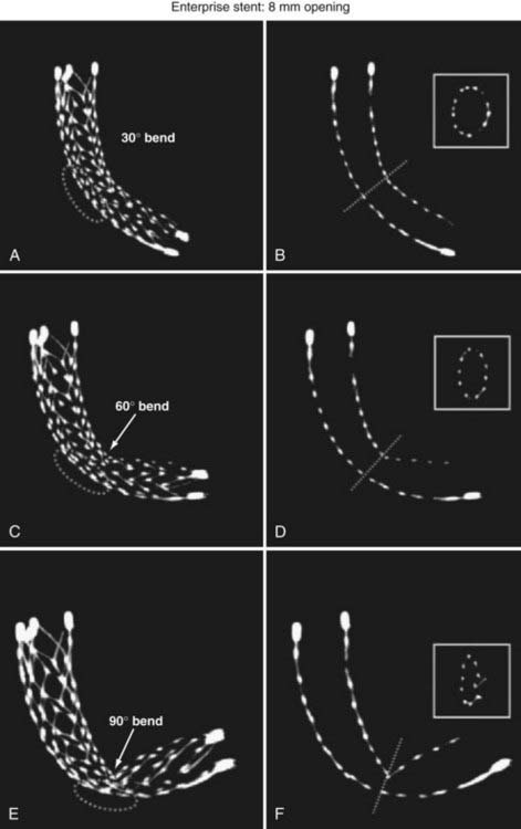
The Enterprise measures 4.5 mm in diameter when unconstrained and as such is only indicated for use in vessels measuring between 2.5 and 4 mm in diameter. The device comes in 14-, 22-, 28-, and 37-mm lengths. The struts of the Enterprise, like those of the Neuroform, are about 60 µm thick. The stent ends are demarcated by four radiopaque markers; the cage portion of the stent is also entirely radiolucent. Enterprise is a closed-cell stent. This provides several key advantages. First, before full deployment, the device is reconstrainable—if the operator judges the deployment of the stent to have started in a suboptimal position, the stent can be reconstrained and repositioned. Second, the closed-cell design prevents the stent from splaying open along the outer curvature of vascular bends. Third, the closed-cell design results in the incorporation of each cell into the entire device structure, making the individual cells more durable and less likely to become damaged during attempted traversal. At the same time, the loss of segmental flexibility created by the continuous closed-cell structure may result in the device kinking or forming a “cobra head” configuration around tight vascular curves (Fig. 376-10), potentially resulting in poor vessel wall apposition and suboptimal parent vessel protection.15,41 The interstices between stent struts are also smaller and less deformable in some anatomic configurations, making the traversal of the device with a microcatheter more difficult in some situations. Finally, although the closed-cell structure provides higher radial resistive force (i.e., resistance to outward compression once deployed), it also exerts less chronic outward force (i.e., outward pressure on the vessel wall), potentially making it more prone to migration during attempted catheterization of the aneurysm or, in some anatomic configurations, spontaneously.43

FIGURE 376-10 Kinking of a closed-cell stent with increasing vascular curvature. Maximal-intensity projections derived from dynaCT (Siemens Medical Solutions, Erlangen, Germany) source data showing the configuration of the Enterprise stent (Cordis Neurovascular/Johnson and Johnson, Warren, NJ) when deployed in tubes (A, C, E, section thickness of 5.0 mm; B, D, F, section thickness of 1.0 mm) with different degrees of angulation. With increasing angulation, the cage demonstrates progressive degrees of kinking. When bent to an angle of 90 degrees, the midportion of the stent forms a “cobra head” configuration with an ovoid appearance when viewed in cross section. In this configuration, the stent would not be expected to appose the walls of the parent vessel and may not provide adequate parent vessel protection during aneurysm embolization.
(From Ebrahimi N, Claus B, Lee CY, et al. Stent conformity in curved vascular models with simulated aneurysm necks using flat-panel CT: an in vitro study. AJNR Am J Neuroradiol. 2007;28:823-829.)
Current Indications
The SEIMs have become incorporated into routine clinical practice for the treatment of wide-necked intracranial aneurysms. The availability of these devices has increased the scope of lesions amenable to endovascular therapies.14,44 As they have become available, an increasing number of different applications of these devices have been innovated.
Stent-Assisted Coil Embolization
There are two general approaches to standard stent-assisted coil embolization—trans-stent coiling and “jailing”45 (Video 376-1, Part 2).
Animation depicts transstent coiling. After the Neuroform (Boston Scientific, Fremont, CA) is in position, a microwire and microcatheter can be manipulated into the aneurysm. Embolization coils are then introduced into the aneurysm to achieve occlusion. The stent functions to retain the coils within the aneurysm, thereby preventing prolapse into the parent artery. (Provided by and with permission from Boston Scientific.)
The most common technique is trans-stent coiling, in which the SEIM is placed across the neck of the aneurysm. After stent placement, a microcatheter is manipulated across the stent and into the aneurysm, and coil embolization is performed. Transstent coiling may be performed at the time of the initial procedure or during a second procedure (staged technique), typically 4 to 8 weeks after stenting. Some operators prefer the staged technique to allow endothelialization of the stent before attempted coiling. Once endothelialization occurs, the stent may become more stable and less likely to migrate or become damaged during trans-stent manipulation of the microcatheter. Also, in these cases, aneurysm coiling may be performed with the patient on aspirin only, rather than dual antiplatelet medications, possibly lessening the implications of procedural aneurysm rupture during coiling. With the jailing technique, a microcatheter is placed within the aneurysm before stent deployment. As the stent is deployed across the aneurysm neck, the expanding stent “pins” or “jails” the microcatheter within the aneurysm. This technique avoids having to manipulate a microcatheter across a newly introduced (and possibly unstable) stent. However, it is not uncommon that the intra-aneurysmal catheter gets displaced during manipulation of the stent delivery system across the aneurysm neck, resulting in loss of position within the aneurysm. Also, if the microcatheter gets pushed out of the aneurysm during coiling, it becomes difficult to recatheterize the aneurysm; and it is possible that the partially introduced coil can become caught between the stent and the vessel wall, leading to coil stretching or breakage and possibly damage or displacement of the stent. If the jailing technique is to be used, the operator must be vigilant about these possibilities.
Rescue and Salvage
During coil embolization, it is possible for detached coils or the entire coil mass to become inadvertently displaced from the aneurysm into the parent artery. In these cases, a SEIM can be navigated across the herniated coil and deployed to either displace the coil mass back into the aneurysm fundus or tack up the displaced strands of coil against the vessel wall to prevent further migration and decrease their intravascular surface area available to function as a source of distal emboli44,46 (Fig. 376-11).

FIGURE 376-11 Stenting for rescue and salvage of a prolapsed coil. A, Subtracted image from a right internal carotid angiogram in a patient with subarachnoid hemorrhage demonstrates a large right posterior communicating artery. B, During coil embolization, a loop of coil prolapsed from the aneurysm into the right internal carotid artery, extending into the carotid terminus. A small amount of thrombus, seen as a lucent filling defect (arrow), accumulated around the end of the herniated coil. A Neuroform stent (Boston Scientific, Fremont, CA) was placed across the herniated coil tail to secure it along the wall of the vessel, prevent further coil prolapse, and provide parent vessel protection for further coil embolization. Native (C) and subtracted (D) images show the Neuroform stent in position, securing the coil against the vessel wall. A loading dose of abciximab was given intra-arterially to prevent stent thrombosis and to lyse accumulating thrombus around the coil tail. The aneurysm was then coiled to complete occlusion.
Balloon-Assisted Coiling Followed by Stenting
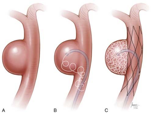
Some operators prefer to begin the coiling of wide-necked aneurysms using a balloon-assisted technique, with stent placement occurring later during the case. In these cases, the stent is placed after coiling to stabilize the coil mass and avoid delayed migration of coils into the parent vessel, to act as a scaffolding within the parent artery to facilitate endovascular remodeling of the aneurysm neck, and potentially to induce some degree of flow redirection (Fig. 376-12).

FIGURE 376-12 Stenting at the conclusion of coiling. In many cases, it can be advantageous to coil an aneurysm with a balloon-assisted technique before stenting. A, A subtracted image demonstrates a small, wide-necked, left vertebral artery aneurysm. Initial coiling was performed using a balloon-assisted technique. B, A “blank roadmap” performed after the introduction of the embolization coils shows a lucent defect corresponding to the deflated balloon catheter. The coil mass remains in position without prolapse into the parent artery. Given the wide-necked configuration of the aneurysm, it was elected to place a stent to stabilize the coil mass at the conclusion of the embolization. So, after balloon-assisted coiling, a Neuroform stent (Boston Scientific, Fremont, CA) has been placed across the aneurysm. Native (C) and subtracted (D) images demonstrate complete occlusion of the aneurysm by the dense coil mass with the in situ Neuroform stent extending across the region of the aneurysm neck.
Advanced Techniques
Y Stent
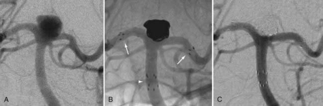
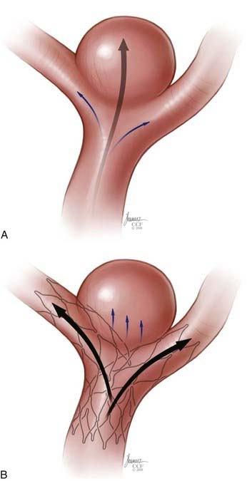
In some cases, a single stent is insufficient to provide parent vessel protection for coil embolization. This situation is most commonly encountered with bifurcation aneurysms arising from the basilar apex or carotid terminus. In these instances, two stents can be placed, the first extending out one limb of the bifurcation and the second introduced through the interstices of the first stent, extending into the other limb of the bifurcation. This configuration forms a Y-shaped construct at the bifurcation and provides robust support for the coil embolization of terminal aneurysms.16,21,22 This Y-stent technique has also been applied to treat middle cerebral artery aneurysms21 and anterior communicating artery aneurysms (Henry H. Woo MD, personal communication, 2006) (Figs. 376-13 and 376-14).

FIGURE 376-13 Y-stent technique. A 62-year-old woman with an incidental basilar artery apex aneurysm. A, Conventional angiographic imaging demonstrates a wide-necked basilar apex aneurysm incorporating both proximal P1 segments of the posterior cerebral arteries (PCAs). B, Unsubtracted posteroanterior imaging after treatment demonstrates the Neuroform stents (Boston Scientific, Fremont, CA) in place, extending from the distal basilar artery into the right and left PCAs, respectively. Two sets of four proximal markers are seen within the distal basilar artery (arrowhead), with single sets of four radiopaque markers within each PCA (arrows). C, Follow-up control angiography at 1 year demonstrates complete occlusion of the aneurysm with durable stent reconstruction of the basilar apex.

FIGURE 376-14 Schematic of Y-stent reconstruction achieving flow diversion. Terminal aneurysms involving the basilar apex and intracranial carotid bifurcation are particularly prone to recanalization because of the “water hammer” effect produced by the direct flow jet from the parent artery into the aneurysm. A, The basilar apex aneurysm depicted shows a dominant flow jet (arrow) toward the aneurysm dome. B, After Y-stent reconstruction, the flow jets (larger arrows) are diverted primarily into the posterior cerebral arteries. The dominant flow jet into the basilar apex aneurysm is disrupted by the construct (small arrows).
Stenting across the Circle of Willis
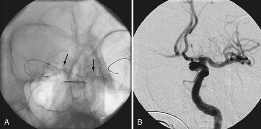
In some cases, the creation of a Y construct is challenging or impossible owing to the anatomy of the vessels as they arise from the distal bifurcation. In these cases, it is sometimes possible to accomplish a reconstruction of a terminal bifurcation aneurysm by placing a stent across the circle of Willis—such as from P1 to P1 through the posterior communicating artery, from A1 to M1 through the anterior communicating artery, or from the ipsilateral A1 to contralateral A1 through the anterior communicating artery.19 This technique provides a means by which to achieve protection of both limbs of the bifurcation with a single SEIM (Fig. 376-15).

FIGURE 376-15 Stenting across the circle of Willis. A 66-year-old woman with a left internal carotid artery (ICA) terminus aneurysm. Clipping of the aneurysm had been attempted at an outside institution but was unsuccessful. A, Unsubtracted angiographic imaging from a left ICA injection demonstrates the Neuroform stent (Boston Scientific, Fremont, CA) in position (arrows indicate end markers), spanning from the left A1 across the neck of the aneurysm into the left M1. The stent had been introduced through the right ICA with subsequent trans-stent coil embolization. B, Subtracted angiographic imaging demonstrates near-complete obliteration of the aneurysm, with minimal interstitial filling noted within the medial aspect of the coil mass.
(From Kelly ME, Turner R, Gonugunta V, et al. Stent reconstruction of wide-necked aneurysms across the circle of Willis. Neurosurgery. 2007;61[Suppl 2]:249-255.)
Waffle-Cone Technique
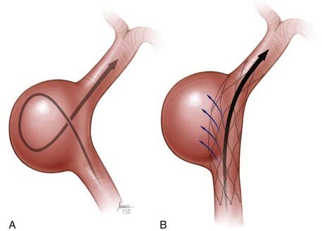
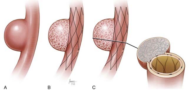
Rarely, Y-stent reconstruction and stenting across the circle of Willis are not technically feasible for the treatment of a wide-necked terminal aneurysm. In these situations, some investigators have deployed a stent from the parent artery directly into the aneurysm (i.e., “intra-extra-aneurysmal stent placement”) to achieve parent artery protection. Using this technique, a single stent can be used to stabilize an intra-aneurysmal coil mass.47 However, the final construct sets up a vector of flow redirection directly into the terminal aneurysm sac and actually disrupts flow into the bifurcation branches. One might expect that such a construct could lead to high rates of recanalization. In addition, if this technique fails or leads to recanalization, other available means of treatment (surgical clipping, endovascular therapy with balloon remodeling, or Y-stent reconstruction) are made considerably more difficult, if not impossible.

Stay updated, free articles. Join our Telegram channel

Full access? Get Clinical Tree

