and Colin L. W. Driscoll2
(1)
Department of Otolaryngology – Head and Neck Surgery, Stanford University, Stanford, CA, USA
(2)
Department of Otorhinolaryngology, Mayo Medical School, Rochester, MN, USA
Room Layout
1.
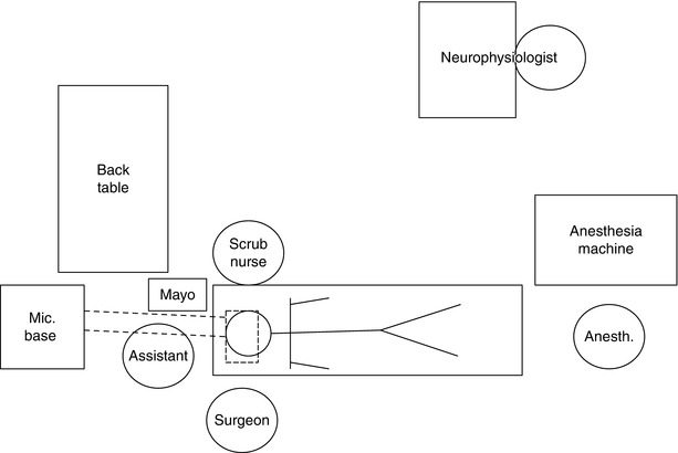
Room layout for an approach on the right side. The bed should be turned 180° from the anesthesiologist to allow maximum room around the patient’s head. Having the microscope base at the head of the bed allows the assistant to sit under the boom arm and observe through the side arm. The scrub nurse sits across the patient from the surgeon to facilitate the handing of instruments. He/she can have a Mayo stand near the patient’s head to hold the commonly used instruments, cottonoid patties, Surgicel, and Gelfoam. All of the rest of the less frequently used instruments can be kept on the back table.
The neurophysiologist can realistically be placed anywhere in the room. However, he/she should be close enough so that the surgeon can communicate with the neurophysiologist and be able to hear the speaker from their machine.
Your anesthesia colleagues may initially not be enthusiastic about being away from the head of the bed but will adapt. The sooner after induction of anesthesia that the table can be turned, the sooner the case can be started. An experienced team should be ready to make an incision 45 min after the patient enters the OR. Once the OR table is turned, multiple people can work simultaneously to place an arterial line, Foley catheter, or EMG monitoring electrodes and to work on patient positioning.
Use of the Mayfield Head Holder
2.
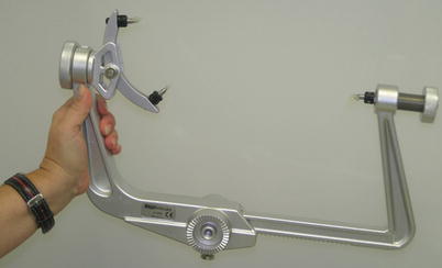
A Mayfield head holder serves two important purposes. First, it rigidly fixates the head so it will not move relative to the operating table. Second, it allows for the attachment of adjustable retractors. We typically use the Greenberg retractor system or the Budde Halo system. By rigidly connecting the table, the head, and the retractor, there is less opportunity for unexpected movements to occur during the surgery. While not every skull base surgery needs the use of the Mayfield, it is often helpful in long cases or those where careful brain retraction is expected.
The Mayfield has three pins. To securely clamp the head, the two pins are typically placed near the back of the head and must be seated above the nuchal line (the horizontal ridge of bone in the back of the head where the posterior paraspinal muscles attach). Ideally, pinning is performed so that one of these two pins is placed under the head to reduce the risk of gravity pulling the patient’s head out of the pins during the long surgery. After first making sure the two pins are firmly in contact with the head, the side with the single pin is then clamped down near the front of the head. Before pinning the patient, bacitracin ointment is applied to the three pins. Also, the anesthesiologist should be warned. The stimulation associated with pinning can often require additional sedation.
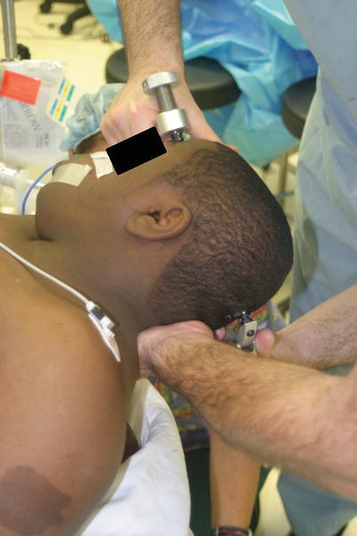
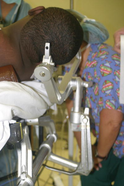
3.
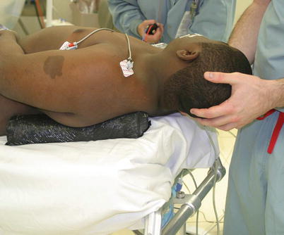
Pinning must be performed carefully so as not to traumatize the patient’s neck or brachial plexus with overstretching. In this example, the patient was pinned for a retrosigmoid approach for vestibular schwannoma resection. Note the large café au lait spot consistent with this patient’s diagnosis of neurofibromatosis type II. A shoulder bump was placed to help rotate the torso slightly.
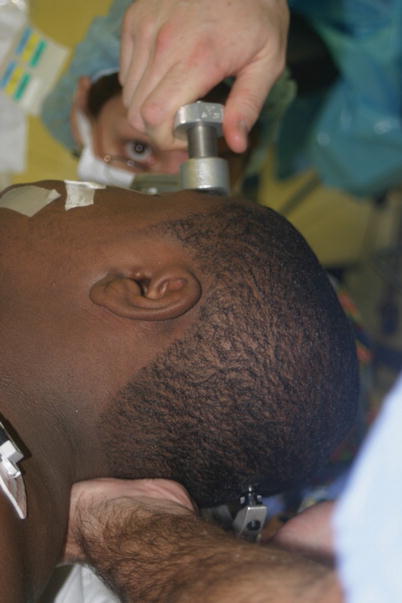
4.
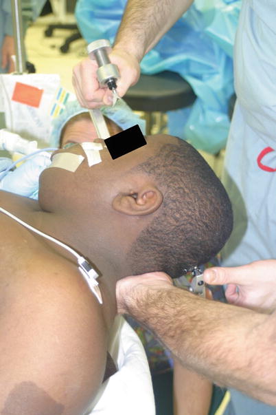
The posterior two pins are seated first to ensure that they both make firm contact with the skull above the nuchal line. During this process, the person applying the pins must be sure not to accidentally poke the hand of the person holding the patient’s head. Note the glob of bacitracin ointment on the anterior pin.
5.
Next, the single pin is brought in. With lateral skull base surgery, this pin often needs to be placed in the forehead. While this is not ideal because of the postoperative pigmentation that can occur in that spot, it is not worth the risk of trying to move the pin to a hair-bearing area. It will not hold the head tightly, and the head may slide out of the pins during the long surgery.
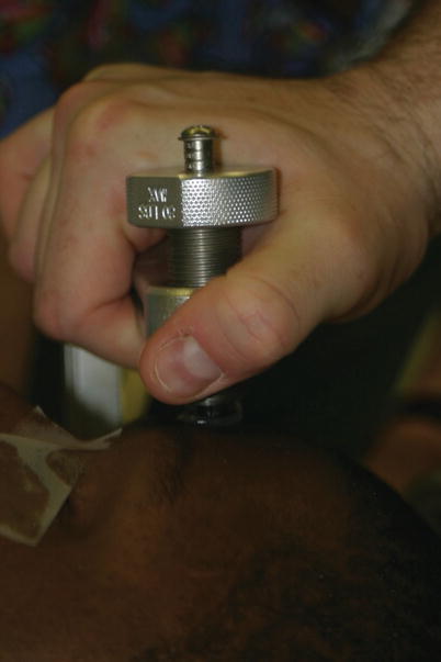
6.
The screw is turned to tighten the pins.
7.
For adults, the screw should be tightened until the third line is reached (60 lbs pressure). When pinning children, shorter pins are used, and the pressure is lowered to prevent a skull fracture.
8.
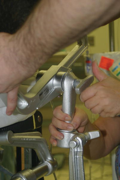
Finally, the head is placed in the proper position. The surgeon must think about what view he/she wants during surgery before finalizing the head position. Typically, we like to have the head flat and tilted forward slightly to keep the operative field as far away from the shoulder as possible. However, care should be taken to make sure that a hand can fit between the patient’s chin and shoulder. If space is not left here, a brachial plexus stretch injury can occur. Head and neck positioning is important when using the Mayfield head frame. Although the OR table can be tilted, every effort should be made to properly position the patient to minimize the need to tilt the bed. There is increased risk of a compressive neuropathy or of falling off the bed when it is tilted, particularly for prolonged procedures.
The screws are tightened at each joint, working from the top down. Before releasing the head, verify the integrity of the Mayfield head holder by trying to jiggle the head slightly. It should not move at all.
9.
The final view of the patient after placing the Mayfield head holder.
Computer-Guided Stereotactic Navigation
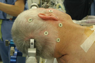
10.
A typical setup for a Stealth navigation system is shown here. The patient has already had an MRI and/or CT scan with the fiducials in place. The Mayfield head holder is placed. Then, each fiducial is located using the computer software. After this has been done, the fiducials can be removed.
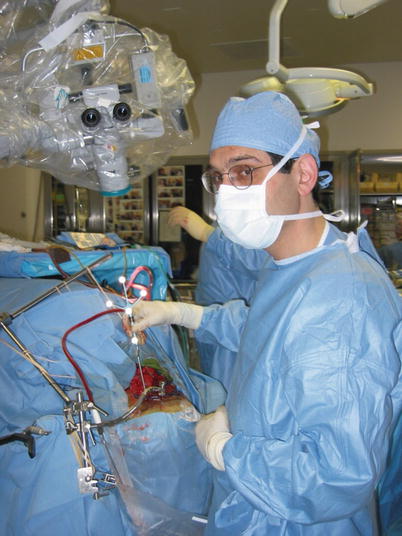
11.
During surgery, the Stealth probe is used to identify the anatomic position of structures noted intraoperatively. This is particularly helpful when assessing structures fixed to the skull as they do not shift position as do structures within or attached to the brain. One minor problem with the Stealth system is that the microscope must sometimes be moved out of the way to fit the probe into the wound. Finding an appropriate position for the viewing screen and other stereotactic navigation equipment can be challenging in smaller ORs.
Cranial Nerve Monitoring
12.
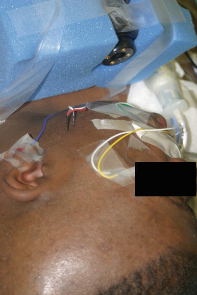
A typical setup for facial nerve monitoring is shown here. This is what we use for routine ear surgery and cochlear implant. The automated facial nerve monitoring machine is used instead of a dedicated neurophysiologist. The paired electrodes (red and blue) are placed at the corner of the eye and mouth. They are placed in a subdermal position, meaning that they do not penetrate deep, just parallel to the skin. There is no significance to whether the red or blue paired electrode is placed at either the corner of the eyes or the corner of the mouth. In either case, activation of the orbicularis oculus and orbicularis oris muscles will be detected. The ground for the recording electrode (green) and the ground for the stimulating electrode (white) are placed anywhere on the chest.
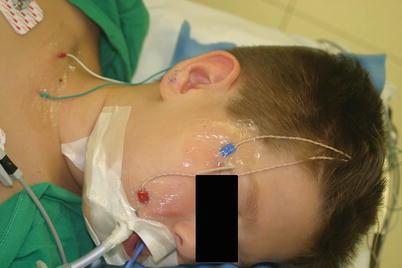
13.
When skull base surgery is to be performed, we always use a neurophysiologist. At a minimum, we measure cranial nerves V, VII, and XI. In this example, where we were doing a hearing preservation middle fossa approach, we also measured ABRs. The facial nerve electrodes were placed at the corner of the eye and mouth. Also, the electrodes for the masseter muscle (CN V) are visible in the midcheek region. Lastly, the electrode for the ABR was placed in the earlobe.
14.
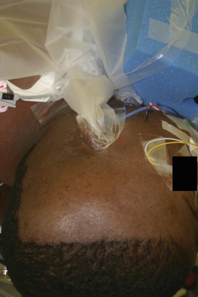
Next, the earphone was placed in the ear canal. Sound travels through the blue tube, and care needs to be taken that the tubing will not become kinked during the case. After applying Mastisol, a sticky drape was applied around the ear to keep the ear canal dry. This is important because if blood or fluid gets into the ear canal, it can cause a conductive hearing loss and abolish the ABR tracing.
CSF Management
15.
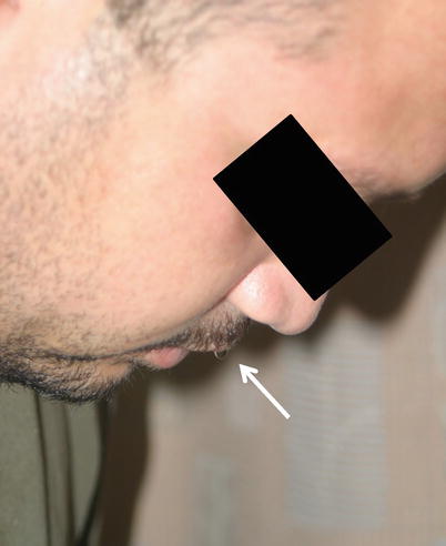
After skull base surgery, patients can have CSF rhinorrhea. This occurs when the dura is not closed in a watertight fashion (as is common after skull base procedures). CSF can percolate through the air cell tracts in the temporal bone and reach the middle ear space. It will then drain down the Eustachian tube and enter the nasopharynx. When the patient is lying back in bed, he/she may notice a salty-tasting drainage, but most often, they won’t appreciate this. By having them lean forward, the presence of CSF rhinorrhea can be diagnosed by visually seeing the CSF drip out of the nose. In this representative patient, the CSF trickled down his mustache (arrow) before dropping to the floor. To treat this, a lumbar subarachnoid drain (LSAD) can be placed.
16.
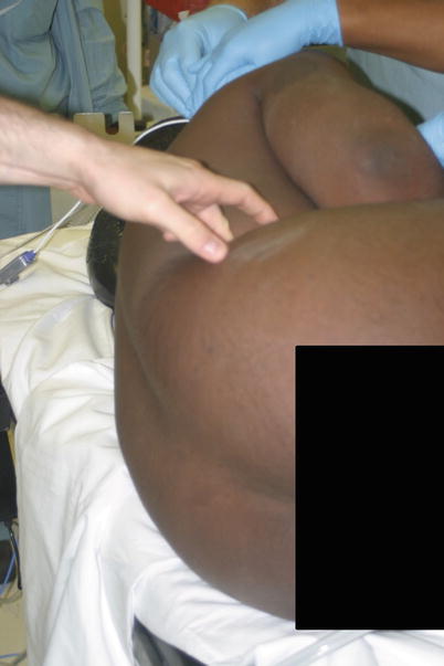
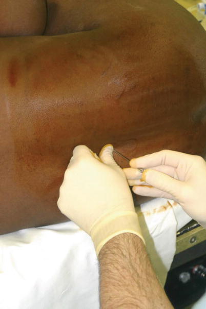
In this example, a postoperative CSF leak was expected because the patient had a very large tumor, and so a LSAD was placed in the operating room before the surgery was started. It was used during the postoperative period to help prevent a CSF leak from developing. First, the patient is turned on his side, and the iliac crest is palpated as a landmark.
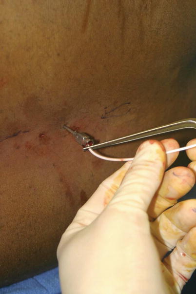
17.
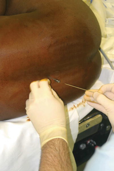
The area is prepped in a sterile fashion, and the space between L3 and L4 is found. The trocar from the LSAD kit is inserted into the interspace at a slight superior angle of approach. The bevel of the trocar is oriented vertically to minimize trauma to the dura when it is penetrated.
18.
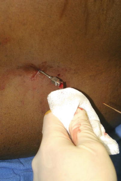
Periodically, the inner cannula is removed to see if CSF is flowing. If it is not, the cannula is reinserted, and the trocar is advanced further. Sometimes but not always, a very slight “give” is felt when entering the intradural space.
19.
When CSF flows, the trocar is turned 90° so that its bevel is oriented superiorly (cephalad).
20.
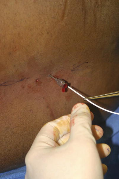
The catheter is then gently inserted and advanced at least 10 cm beyond the tip of the trocar.
21.
The trocar is then carefully removed, and flow of CSF through the catheter is verified. If it is working, the catheter is sutured to the back in two different locations. A sterile dressing is applied. For extra safety, the catheter is also coiled twice and secured to the skin next to the entry point with a large Tegaderm.
Instrumentation
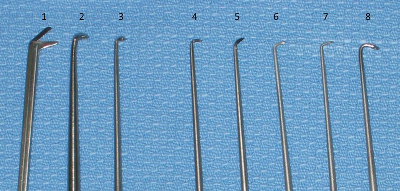
22.
Skull base surgery requires a standard craniotomy set, a neurotology set, and a fat graft set. Some of the specialized microdissectors in the neurotology set are shown in the picture. The purpose of the microdissectors is mainly to allow careful dissection of tumors off the cranial nerves and out of the internal auditory canal. (1) Angled scissors. (2–3) Microcurettes allow removal of residual tumor that rests under a lip of bone, typically the lateral aspect of the internal auditory canal. (4–5) Angled knives allow the dura of the internal auditory canal to be opened in a careful and precise manner without disturbing the tumor or nerves that may lie directly underneath. (6–8) Smaller microcurettes at various angles allow probing of the fundus of the internal auditory canal to verify that all the tumor has been removed.
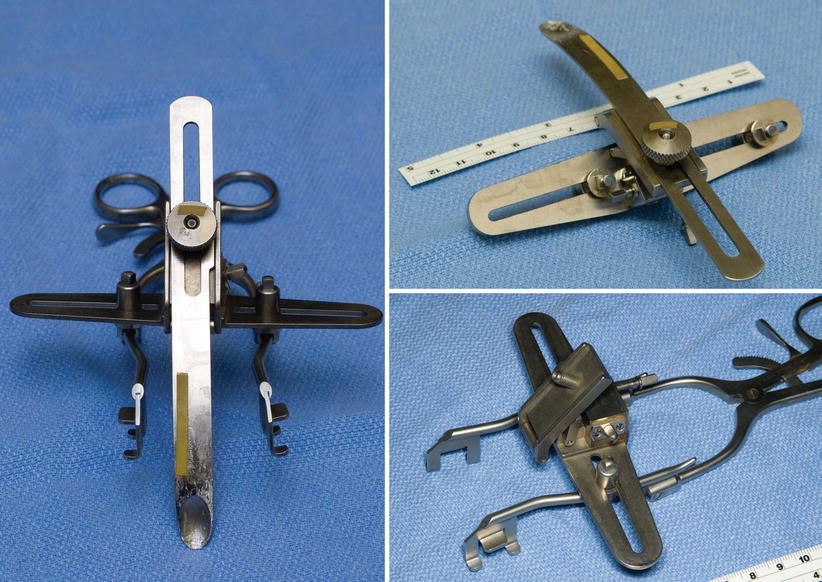
23.
Three views of a custom-modified version of the House-Urban and Fisch retractors. Such a device can be used instead of malleable retractors and the Greenberg retractor set for middle fossa approaches if desired.
A list of the contents of our instrument sets are given below in the following tables:
Craniotomy set
Manuf | Prod Num | Inst/Cmt | Qty |
|---|---|---|---|
Codman | 50-1194 | Retractor Weitlaner Small Sharp 3 × 4 5 1/8″ | 2 |
Codman | 50-1020 | Retractor Vein Large 13 mm
Related posts:Stay updated, free articles. Join our Telegram channel
Full access? Get Clinical Tree
 Get Clinical Tree app for offline access

|
