Fig. 4.1
Electrodes used for microelectrode recording (MER). (a) MER performed using the electrode tip (arrowhead) as the recording electrode and the tip of the outer sheath (arrow) as the indifferent electrode. (b) The recording electrode has been withdrawn, leaving only the outer sheath. The tip of this sheath is used as the stimulating electrode for intraoperative stimulation
4.2 MER Devices, Electrodes, and Recording Systems
The LeadPoint® (Medtronic, Japan; Fig. 4.2a) is one of the best known recording systems manufactured specifically for use in DBS surgery. Similar to most systems, the LeadPoint® incorporates a special microelectrode drive and micromanipulator to advance the electrodes in fine increments (microTargeting™ drive, Medtronic; Fig. 4.2b). This system can be adapted for simultaneous multitrack recording, which is described below. Medtronic recording electrodes (Fig. 4.1) typically have a resistance of 1.0 MΩ (at 1,000 Hz) and a diameter of 10 μm at the tip. MER is performed using the tip of the microelectrode sheath (length 1 mm) as the indifferent electrode, which can also be used as the stimulating electrode for intraoperative test stimulation.
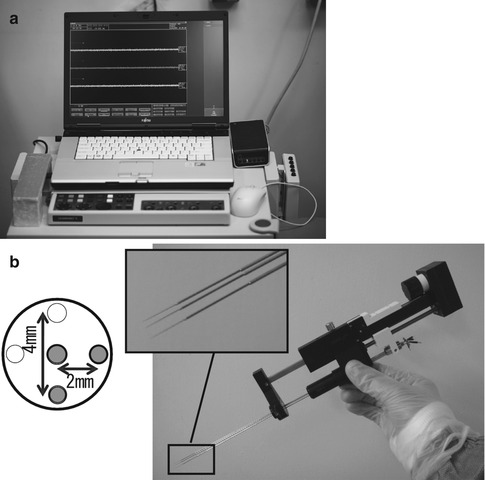
Fig. 4.2
Microelectrode recording (MER) system. (a) External appearance of the LeadPoint® system (Reprinted with the permission of Alpine Biomed ApS). (b) Right: MicroTargeting™ Drive system comprising an electrode holder and a micromanipulator for inserting the electrode. Top left: Pattern diagram of multitrack electrodes. In addition to a central electrode, other electrodes can be simultaneously inserted in the 0, 3, 6, and 9 o’clock positions. In this example, three electrodes (the central electrode and two others at 3 and 6 o’clock positions) have been fitted in the holder (Reprinted with the permission of FHC, Inc.)
4.3 Target Identification for MER
MER is performed while using a manipulator to gradually advance the microelectrode toward the target sites identified prior to the surgery. Typically, the microelectrode is advanced to its final location from a point approximately 10–20 mm away the target site. To decrease the risk of hemorrhage, the recommended speed of microelectrode advancement is ≤0.5 mm/s (Binder et al. 2005). The target sites are confirmed by using neurophysiological factors such as the background activity level, changes in neuronal discharge patterns, and neural activity in response to peripheral sensory stimulation. The target sites for DBS typically include the cortex–basal ganglia pathways. Because the neural activity in the basal ganglia varies with different disorders, the characteristics of neural activity identified using MER also will differ depending on the disease.
4.3.1 Subthalamic Nucleus (STN) (Fig. 4.3)
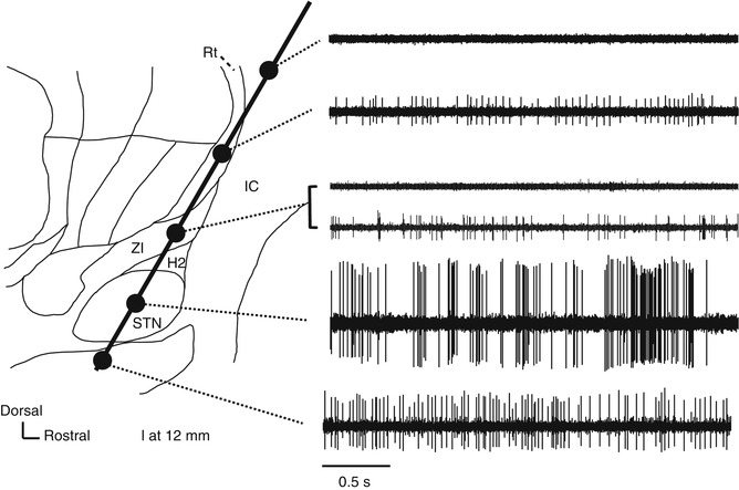
Fig. 4.3
Neural activity recorded along the insertion route to the subthalamic nucleus superimposed on a sagittal section (12-mm lateral) from the Schaltenbrand–Wahren atlas. H2 H2 field of Forel, IC internal capsule, Rt reticular thalamic nucleus, STN subthalamic nucleus, ZI zona incerta
STN is commonly targeted for DBS treatment of Parkinson’s disease (PD). When the recording microelectrode is targeted toward STN at an angle of 50–60° to the anterior commissure (AC) and the posterior commissure (PC) line (viewed in a sagittal section), it typically passes through the thalamus, zona incerta (ZI), H2 field of Forel, STN, and substantia nigra pars reticulata (SNr). ZI is dorsally surrounded by the thalamic fasciculus (the H1 field of Forel) and ventrally surrounded by the lenticular fasciculus (H2 field of Forel). Because the cell density is higher in STN than in these other structures, STN can be identified using MER because of its high background activity and frequent spontaneous discharges. A microelectrode targeting STN also will pass through the thalamic subnuclei, including the nucleus reticularis and the nucleus ventralis oralis (Vo nucleus), where irregular firing at approximately 10–30 Hz is evident. Compared with the nucleus ventralis intermedius (Vim nucleus), there is little spontaneous discharge in these thalamic subnuclei, and their amplitudes are low. When the angle of insertion viewed in a sagittal plane is small (when insertion is performed from the front), the electrode does not pass through the thalamus but through the internal capsule, where few action potentials are recorded because of the dense white matter. In the thalamus, low-threshold spike (LTS) bursts are often recorded (Kim et al. 2009; Kobayashi et al. 2009) (Fig. 4.4). After exiting the thalamus and entering the white matter of ZI/H2 field of Forel, both background activity and spontaneous neuron discharge decrease. Spontaneous discharges with moderate amplitudes may be recorded in ZI. When the electrode is advanced further, background activity increases and high-amplitude action potentials are recorded, indicating that the microelectrode tip has reached STN. Typically, STN neurons have high spontaneous activity with irregular bursts (Bezard et al. 1999) and can fire at rates >30 Hz in PD (Hutchison et al. 1998; Steigerwald et al. 2008; Schrock et al. 2009). The dorsolateral region of STN is a sensorimotor region that receives input from the primary motor area of the cerebral cortex. STN neurons in this region respond with a change in firing frequency to passive joint movement of the contralateral limbs, and they are somatotopically arranged into regions for the upper and lower limbs, arranged from the lateral to the medial side (Rodriguez-Oroz et al. 2001). This neural organization is helpful for assessing the microelectrode position in the lateromedial direction (X-axis). After the microelectrode passes through STN, it reaches the white matter on the dorsal side of SNr, which is indicated by a decrease in background activity in MER. This white matter is only a few hundred microns thick (up to approximately 3 mm) and is often not identified before the electrode enters SNr. Although it may be difficult to distinguish between SNr and STN, SNr exhibits a somewhat higher firing frequency (50–70 Hz) than STN and shows a regular discharge pattern with few bursts.
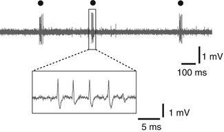
Fig. 4.4
Low-threshold spike (LTS) burst (circle) recorded in the thalamus
4.3.2 Thalamus
The thalamus is often the target in DBS for the treatment of tremors. On the ventrolateral part of the thalamus, located from anterior to posterior, are the Vo nucleus, Vim nucleus, and nucleus ventralis caudalis (Vc nucleus). Neural activity recorded in the Vim nucleus generally shows a greater frequency than that recorded in the Vo nucleus; however, it is often difficult to determine the border between these two structures using MER alone. In general, MER is only used to identify the Vim–Vc border, which provides a standard for estimating the positions of other nuclei, according to a human brain atlas. The posterior and anterior limits of the Vim nucleus on the AC–PC line are situated at 2/12 and 3/12 of the length of the AC–PC line, anterior to PC (Benabid et al. 1996). When the microelectrode is inserted toward PC at an angle of approximately 45° to the AC–PC line (viewed in the sagittal plane), it passes through the Vim to the Vc along a path that crosses the Vim–Vc border. On this path, MER can identify neurons that respond to joint movement of the contralateral limbs (by a change in firing frequency) and discharge rhythmically at the same frequency as tremors are recorded in the Vim nucleus. Neurons that fire rhythmically at the same frequency as tremors are known as “tremor cells” (Fig. 4.5) and are thought to be associated with the generation of tremors. They are often recorded within the Vim nucleus of the thalamus but may also be recorded in the Vc and Vo nuclei (Lenz et al. 1994; Katayama et al. 2005). In terms of the somatotopy of neurons responding to joint movement, this somatic localization is distributed into regions for the upper and lower limbs arranged from the medial to the lateral side (Lenz et al. 1988). Further advancement of the microelectrode reveals MER from neurons responding to light tactile stimulation of the skin, which indicates that the electrode has entered the Vc nucleus, which receives input from the medial lemniscus. The Vim–Vc border is physiologically defined as the most anterior neuron along a length of trajectory in which more than one-half of the neurons located posteriorly were neurons responding to sensory stimulation (Hua and Lenz 2005) (Fig. 4.6). Somatotopy within the Vc nucleus is similar to that within the Vim nucleus, with the lower limb region located on the lateral side, the upper limb region located medially.
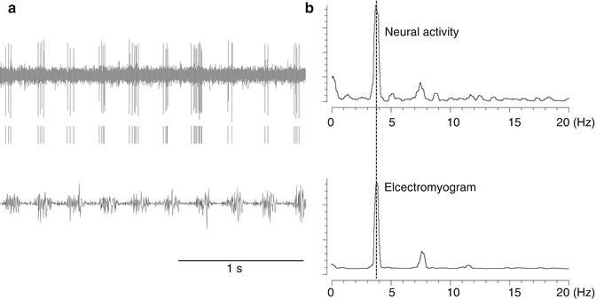
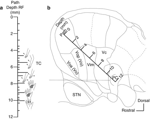
Fig. 4.5
Neurons recorded in the thalamus that fire at the same frequency as tremors (tremor cells). (a) Top: Neural activity. Middle: Raster display of neuron firing. Bottom: Electromyogram (EMG) of tremors recorded simultaneously. (b) Power spectrum of timing of neuron firing (top) and the frequency of electromyogram (EMG) of tremors (bottom). They both peaked with the same frequency (3.8 Hz)
Fig. 4.6
Identification of the border between the Vim and Vc nuclei (Vim–Vc border). The Vim–Vc border is physiologically defined as the most anterior neuron along a length of trajectory in which more than one-half of the neurons located posteriorly were sensory neurons (Hua and Lenz 2005). (a) Body parts that respond to peripheral sensory stimulation on the insertion route (receptor field: RF). Short line: sites where neuron activity was recorded. Long line: the neurons responding to joint movement or neurons responding to tactile stimulation of the skin. TC tremor cell. (b) A insertion route superimposed on a sagittal section (14.5-mm lateral) from the Schaltenbrand–Wahren atlas. Voa nucleus ventralis oralis anterior, Vop nucleus ventralis oralis posterior, Vim nucleus ventralis intermedius, Vc nucleus ventralis caudalis, STN subthalamic nucleus
4.3.3 Globus Pallidus Internus (GPi) (Fig. 4.7)
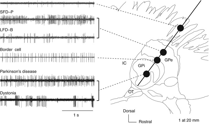
Fig. 4.7
Neural activity recorded along the insertion route toward the globus pallidus internus (GPi) superimposed on a sagittal section (20-mm lateral) from the Schaltenbrand–Wahren atlas. GPe globus pallidus externus, GPi globus pallidus internus, IC internal capsule, LFD-B low-frequency discharge with bursts, SFD-P slow-frequency discharge with pauses, Str striatum
The GPi is a target site for DBS treatment of PD and dystonia. The frequency and pattern of neural discharges in pallidum are thought to vary with different diseases and etiology. Dystonia can be categorized into primary or secondary according to the etiology and as focal, segmental, multifocal, hemi-, and general according to the regions of the body showing symptoms, with varying underlying pathologies. Therefore, MER findings also can differ by the type of dystonia. Here, we focus on primary general dystonia (hereafter simply “dystonia”), which is the type most frequently treated with DBS.
Related posts:
 Mechanism of DBS: Inhibition, Excitation, or Disruption?
Deep Brain Stimulation for Psychiatric Disorders
Symptoms and Signs of Parkinson’s Disease and Other Movement Disorders
Deep Brain Stimulation for Essential Tremor
Surgical Technique of Brain Stimulation
Thalamic Stimulation for Parkinson’s Disease: Clinical Studies on DBS
Mechanism of DBS: Inhibition, Excitation, or Disruption?
Deep Brain Stimulation for Psychiatric Disorders
Symptoms and Signs of Parkinson’s Disease and Other Movement Disorders
Deep Brain Stimulation for Essential Tremor
Surgical Technique of Brain Stimulation
Thalamic Stimulation for Parkinson’s Disease: Clinical Studies on DBS
Stay updated, free articles. Join our Telegram channel

Full access? Get Clinical Tree


