Introduction to Endovascular Equipment
The selection of equipment is a critical step in the planning process for any neurointerventional procedure. As with open surgical procedures, there are few times when only one tool can do the job. Nevertheless, frustration and failure can often be avoided with the careful selection and use of the appropriate devices.
This chapter is designed to provide a detailed description of the design, function, and use of the most commonly employed neurointerventional devices. Tables describing the various permutations of each device are provided as quick reference tools to aid in the selection process. Recommendations regarding the effective use of some devices are also provided.
Preparation
Before any neurointerventional procedure can be started, several items must first be arranged and set up. Throughout the procedure, there is either behind or on the side of the interventionist an equipment table that contains not only a workspace but also space for equipment that may or may not be used later in the case (Fig. 7.1).
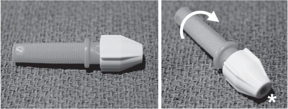
At or near the foot of the bed are the heparinized pressurized flush lines that are connected to the various catheters to prevent stagnation of blood inside them, as well as a power injector with sterile tubing that is placed on the field. These lines must be cleared of all air within them to prevent air emboli through the catheters. Some interventionists choose to use filters to reduce the incidence of air in the flush lines. The flush rate of the catheters is also highly variable, but most interventionists choose 1 drop/second. Lastly, depending on the size of the catheter that is to be flushed, the interventionist may choose to run a micro versus a macro flush line, which can limit the volume going through the catheter in patients who may be sensitive to extra volume during longer cases. The ends of the flush lines are normally connected with the catheters through a stopcock and a Y-Touhy-Borst connector. The stopcock allows a place to connect either syringes of contrast or the power injector line. The Touhy-Borst Y-valve (Fig. 7.2) allows a continuous flow of heparinized saline during either catheter or wire manipulation. This connector also has a rotating adjustable seal that can conform to either the wire or the catheter so that it can still be moved without backflow of saline or blood from the back of the connector.
Several important items are normally located on the equipment table (Fig. 7.1). The essential elements are a sharps container, dry 4×4 gauze pads, wet Telfa pads, towels, wire bowls, smaller cups for either saline or contrast, and a varying array of syringes used for injection of either saline or contrast. The gauze pads, when damp, are useful for wire manipulation. The wet Telfa pad is used for wiping wires so that small blood clots do not form on them and become thromboemboli when a catheter is exchanged over them. Wire bowls, usually one for macrowires and catheters and another for microwires and catheters, are partially filled with saline and are used not only to wet the equipment before use but also to store equipment when it is not in use.
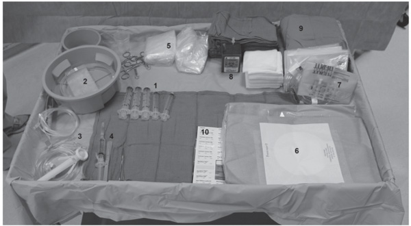
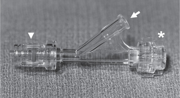
Fig. 7.2 Touhy-Borst rotating hemostatic valve. This is normally connected to the catheters, allowing them to be connected to a continuous flush (arrow). The connector (arrowhead) rotates. The valve (asterisk) can be opened to allow placement of other catheters or wires and turned to provide a secure seal, which does not allow outflow of the saline flush or blood from the catheter.
For vascular access equipment, for example, a micropuncture set, please see Chapter 6. Once access is obtained, the following review describes equipment that will be helpful to formulate a concise and effective neurointerventional plan.
Introducers (Sheaths)
An introducer (sheath) is a small tube that is inserted through the skin and into a vessel to provide access to the intravascular space. Introducers consist of four parts: tip, hub, shaft, and dilator (Fig. 7.3).
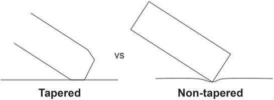
• The tip of the sheath provides an opening into the intravascular space. The tips of most introducers are tapered so that the tip of the sheath does not dig into the vessel wall (Fig. 7.4).
• The proximal end of a sheath is its hub. Most sheaths have a built-in hemostatic valve that prevents blood loss while devices are introduced. A side port, which is accompanied by a stopcock and a flush line, can be used to inject contrast, draw blood for laboratories, or connect to a heparinized saline flush.
• The shaft of the sheath is the tube between the tip and the hub. A sheath is described by the diameter of its working lumen (inner diameter) and the length of its shaft. For instance, a 10 cm 6 Fr introducer has a shaft 10 cm long and will accommodate a device up to 2 mm (6 Fr) in size. The size of the arteriotomy created by the sheath will vary depending on the thickness of the walls of the sheath, but is usually 1–2 Fr larger. It is particularly important to know the outer diameter of the introducer if a closure device will be used.
• The dilator is a removable inner cannula that is coaxially inserted into the sheath while it is advanced through the skin and into the target vessel. It extends from the tip of the introducer and tapers to a soft, blunt tip. The dilator makes it easier to insert the relatively blunt sheath through the skin. It also prevents the walls of the sheath from “snow plowing” into vessel walls when the sheath is advanced (Fig. 7.5).
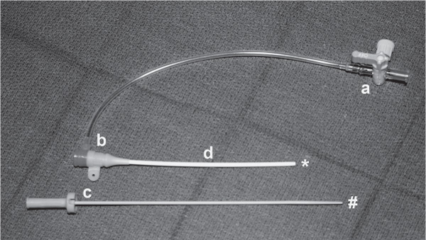
Fig. 7.3 Introducer sheath. The introducer sheath allows multiple types of catheters to be placed and held securely. Each sheath has several notable parts, namely (a) stopcock, (b) hub, (c) introducer stylet/dilator with a rounded tip (pound sign) for minimal trauma upon placement, and (d) sheath shaft with a tapered tip (asterisk).
Recommendations for Selecting the Length of the Introducer
• Short (10 cm) introducers are used for most diagnostic procedures, because they are easy to insert and cause the least damage if inserted incorrectly.
• Medium-length introducers (25 cm) will help to straighten out tortuous iliac anatomy in older patients. Consider using a wider-diameter sheath for even better kink resistance.
• Long introducers (70 cm or more) will provide direct access to the supraaortic vessels and tend to provide more proximal support than guide catheters, because they are stiffer.
• Long armored sheaths can provide additional support in tortuous anatomy but may increase the risk of vessel injury and vasospasm.
• Wet the outside of the introducer to make it easier to push.
• Avoid using a sheath that is too long. Any excess catheter outside the patient effectively lengthens the working distance from the hub to the target position of the microcatheter (Fig. 7.6).
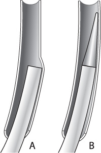
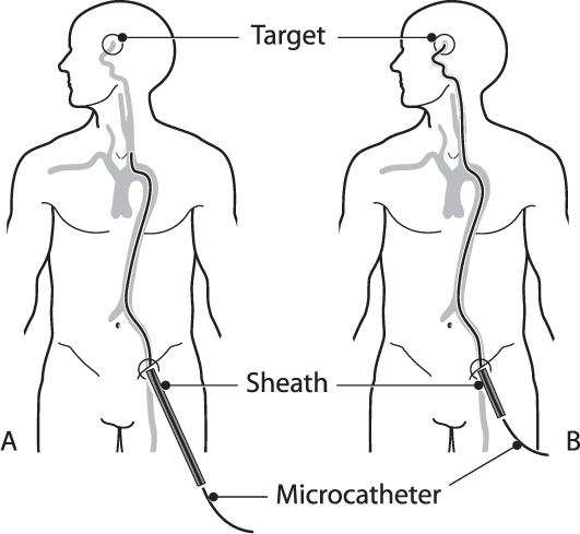
Fig. 7.6 Long sheath. (A) If the sheath is too long for the patient the excess length will lengthen the working distance between the hub and the target. (B) An appropriately sized sheath will protrude less than a few centimeters beyond the skin.
Recommendations Regarding the Diameter of the Introducer
• The sheath must be large enough to accommodate any devices that will be used during the procedure.
• Dual microcatheter techniques and stents will generally require a 6 Fr or larger introducer.
• The introducer must be small enough to fit in the parent vessel without occluding it. Consider more proximal placement of the sheath when accessing smaller vessels.
Catheters
Like introducers, catheters have a tip, a hub, and a shaft. They are inserted through a separate introducer rather than through the skin, so they do not require a dilator. Catheters are generally sized by their outer diameter. This is an important distinction from introducers. A 6 Fr catheter is 2 mm in diameter and will go through a 6 Fr introducer. The tips of catheters are typically straight, pre-shaped, or shapeable either by steam or hand, so that they can be better navigated into the lesion or vessel desired.
Diagnostic Catheters
Almost any catheter can be used for a diagnostic angiogram, but not all are equally safe. Large, stiff catheters are easy to steer and hold their position well when devices are passed through them, but they are more likely to cause a dissection or dislodge an embolus than softer catheters. For most diagnostic procedures in adults, a 4 Fr or 5 Fr diameter catheter with a soft, hydrophilic, non-braided tip is sufficient. 3.2 Fr diagnostic catheters are available for pediatric cases.
Considerations for Diagnostic Catheter Selection
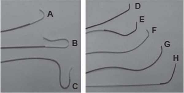
Diagnostic catheters are available in a variety of preformed shapes (Fig. 7.7). Convenience and frugality lead most interventionalists to use a single catheter during a diagnostic procedure. Consider changing out the catheter for a different shape if difficulty is encountered in selecting a vessel.
• In younger patients with a Type I arch, nonrecursive catheter shapes (Fig. 7.7A), such as a multipurpose or Judkins right coronary catheter, can be used with or without a wire to select pre-cerebral vessels efficiently.
• In older patients with more tortuous anatomy (Type II or III arch) or a bovine arch, a recursive catheter shape (Fig. 7.7B) such as the Simmons-2, Newton, or Vitek catheter will make it easier to engage the carotid origin.
• When other catheters fail, consider using a headhunter shape to access the right subclavian and vertebral artery. This shape, combined with a shapeable 0.035 glide wire formed in a large “C” shape, will often select a difficult right subclavian or vertebral artery when other combinations fail.
Guide Catheters
Guide catheters are larger, stiffer catheters through which other, smaller catheters and devices can be passed. A guide catheter gets its support from a braided stainless steel core that runs along the entire length of the catheter. The added stiffness from this core helps to reduce the tendency of the catheter to herniate back into the arch when devices are passed through it.
The stiffness of the guide catheter varies along its length. Proximally, the catheter is stiff to help straighten out tortuous vessels and to provide a safe conduit for passing devices to their intended targets. Distally, a guide catheter is made more pliable to reduce the risk of vessel trauma. Like diagnostic catheters, guide catheters are available with pre-shaped tips to facilitate vessel selection off the arch. However, due to their larger sizes and stiff characteristics, they are manipulated forward only with the presence of a wire or other catheter. There are rare circumstances where guide catheters are manipulated forward without an inner device present.
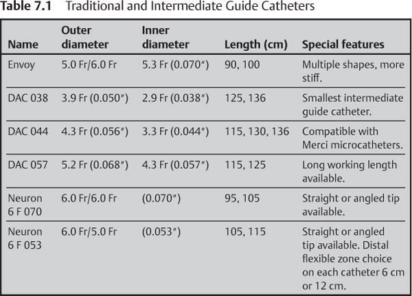
Traditional and Intermediate Guide Catheters
Traditional guide catheters are generally positioned as high up in the target cervical vessel as possible for good support, but they are too stiff to safely pass intracranially. In tortuous anatomy, however, even high cervical placement of the guide catheter may not lend enough support to prevent it from herniating back into the arch while passing stiff devices through it (Fig. 7.8). Intermediate guide catheters, such as the Neuron (Penumbra, Inc.) or the DAC (Concentric Medical, Inc., Mountain View, CA) are soft enough to be positioned intracranially. Like traditional guide catheters, intermediate guide catheters have a braided metal core. In the DAC, the stainless steel braid is softer near the tip to make it less traumatic than a traditional guide catheter. A similar result is obtained with the Neuron guide catheter by transitioning the stiff stainless steel braid in the proximal shaft with a platinum coil at the tip (Table 7.1).
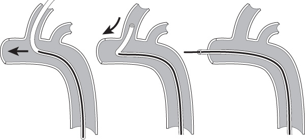
Fig. 7.8 Stiff catheters. Catheters that are too stiff or not in a stable position can be knocked out of a vessel while pushing devices through them.
Balloon Guide Catheters
A balloon guide catheter is similar to a standard guide catheter except that it has an externally mounted compliant balloon at the tip. Currently, the only FDA-approved balloon guide catheter available is the Merci Balloon Guide Catheter (Concentric, Mountain View, CA). This catheter is designed to arrest flow in the internal carotid artery (ICA) during Merci clot retrieval to reduce the risk of distal embolic complications. The Merci Balloon Guide Catheter is available in several sizes and lengths to accommodate balloon occlusion of either the ICA or common carotid artery (CCA) (Table 7.2).
Other Uses of Balloon Guide Catheters
• A balloon guide catheter is a convenient and cost-effective method for performing a test balloon occlusion of the internal carotid artery. Unlike a stand-alone balloon, the lumen of the balloon guide catheter can be continuously flushed with heparinized saline to reduce the risk of thromboembolic complications.
• A balloon guide catheter can slow or stop antegrade flow through the carotid artery while accessing a carotid-cavernous fistula to aid in visualization during angiography.
• Consider using a balloon guide catheter during embolization of high-flow tumors or arteriovenous malformations (AVMs) to slow flow through the lesion during embolization to prevent premature occlusion of the venous drainage system.
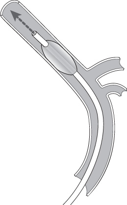
• A balloon guide catheter can arrest and (with aspiration) reverse flow while crossing or stenting the carotid artery as a form of “proximal protection,” particularly when a distal protection device is not feasible (Fig. 7.9).
Recommendations for Choosing a Guide Catheter
• For young adult patients with favorable anatomy, the simplest solution is to use a traditional guide catheter with an angled tip, such as the MPC Envoy (Cordis, Endovascular, Miami Lakes, FL). A guide catheter can be navigated high into the cervical vasculature without performing an exchange or using a separate selection catheter. For extra support, consider using a Simmons-shaped guide catheter. Its curves will gently press against the vessel walls to help hold it in place.
• In tortuous anatomy, consider using a guide sheath. A guide catheter can be placed inside the sheath in a coaxial arrangement for more distal access, if required. Armored sheaths can provide even greater proximal support but have a greater chance of causing vasospasm or dissection.
• Consider an intermediate guide catheter in very tortuous anatomy or in small-caliber vessels where a traditional guide catheter or sheath would be occlusive.
• Avoid using an excessively long guide catheter. If there is an excessive amount of catheter outside the patient, the micro-devices may not be long enough to reach the lesion (Fig. 7.6).
Table 7.2 Merci Balloon Guide Catheters
Outer diameter (proximal) | Inner diameter | Length |
8 Fr (0.105″/2.7 mm) | 0.078″ (5.9 Fr/1.9 mm) | 80 cm |
8 Fr (0.105″/2.7 mm) | 0.078″ (5.9 Fr/1.9 mm) | 95 cm |
9 Fr (0.118″/3.0 mm) | 0.085″ (6.4 Fr/2.1 mm) | 80 cm |
9 Fr (0.118″/3.0 mm) | 0.085″ (6.4 Fr/2.1 mm) | 95 cm |
Microcatheters
Microcatheters are small catheters (less than 3 French) designed for intracranial use. Some common characteristics of microcatheters used for neurointerventional procedures include:
• A tapered shaft with a useable length of ~150 cm.
• A hydrophilic coating to enhance trackability through small vessels.
• A shaft with a braided metal core for torqueability.
• One or two distal markers.
• A pre-shaped tip or tip shapeable with steam.
Classes of Microcatheters
Although alternative classifications exist, perhaps the most functional classification is to separate them based on their size, specifically the outer diameter (OD) of their tips.
• Small microcatheters (less than 1.5 Fr tip) are used mostly for AVM embolizations.
• Medium-sized catheters (1.5–2.0 Fr) are well suited for aneurysm coiling and thrombolysis procedures.
• Large catheters (between 2.0 and 3.0 Fr) are used to deliver large coils, particles, clot-retrieval devices, and intracranial stents.
Small Microcatheters
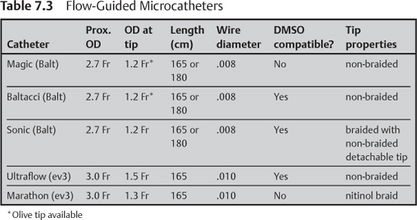
The smallest class of microcatheters has an outer diameter below 1.5 Fr (Table 7.3). They are used for liquid embolic materials, most commonly in the treatment of AVMs or vascular tumors. These small microcatheters are frequently referred to as “flow-guided” catheters, although most can be used in conjunction with a microwire for additional control.
Nonbraided Small Microcatheters
• They generally have the smallest tips available.
• They follow the direction of blood flow without wire guidance and essentially float to high-flow lesions, such as AVMs.
• Some of these catheters have a small “olive” at the tip to enhance their flow-guided properties. The olive will also arrest flow in the target vessel once it wedges into place to facilitate embolization.
• They can be damaged or perforated if used with a microwire.
• Their low burst pressure may result in catheter rupture when injecting viscous embolic agents.
Braided Small Microcatheters
• They have a stainless steel proximally for support; some have a braided nitinol tip for flexibility.
• They can be safely guided over a microwire.
• They exhibit some flow-guided characteristics.
• They have higher burst pressure than non-braided microcatheters.
Hybrid Small Microcatheters
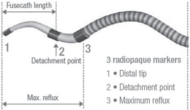
• The Sonic microcatheter (Balt) is a braided microcatheter with a 15 mm non-braided microcatheter fused to its tip. This hybrid construction allows the Sonic microcatheter to retain the small tip size of a non-braided catheter while maintaining the superior burst strength of a braided microcatheter. If the non-braided end is accidentally glued into place, it can be safely snapped off with gentle traction, allowing the rest of the catheter to be removed (Fig. 7.10).
• Ultraflow (ev3, Plymouth, MN) is also a hybrid microcatheter with a non-braided distal portion to allow for flow-guided navigation. This microcatheter is not designed to have a detachable tip.
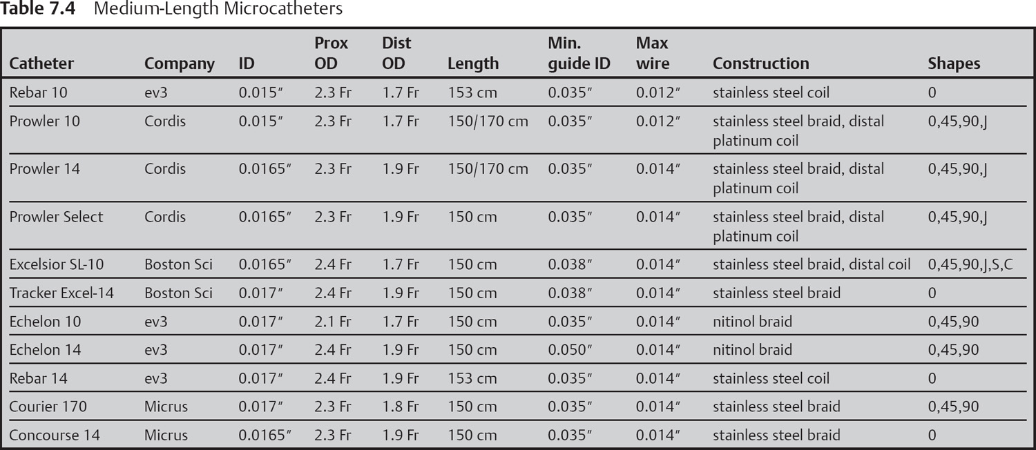
Medium-sized Microcatheters (Table 7.4)
• They have tip diameters between 1.7 to 1.9 Fr.
• They are reinforced with a metal braid or coil for better stability and pushability.
• They are too stiff to be flow-guided in most circumstances, so they are usually steered using a guidewire.
• They hold their position better than small microcatheters to make it easier to deploy coils.
• Many have pre-shaped or shapeable tips.
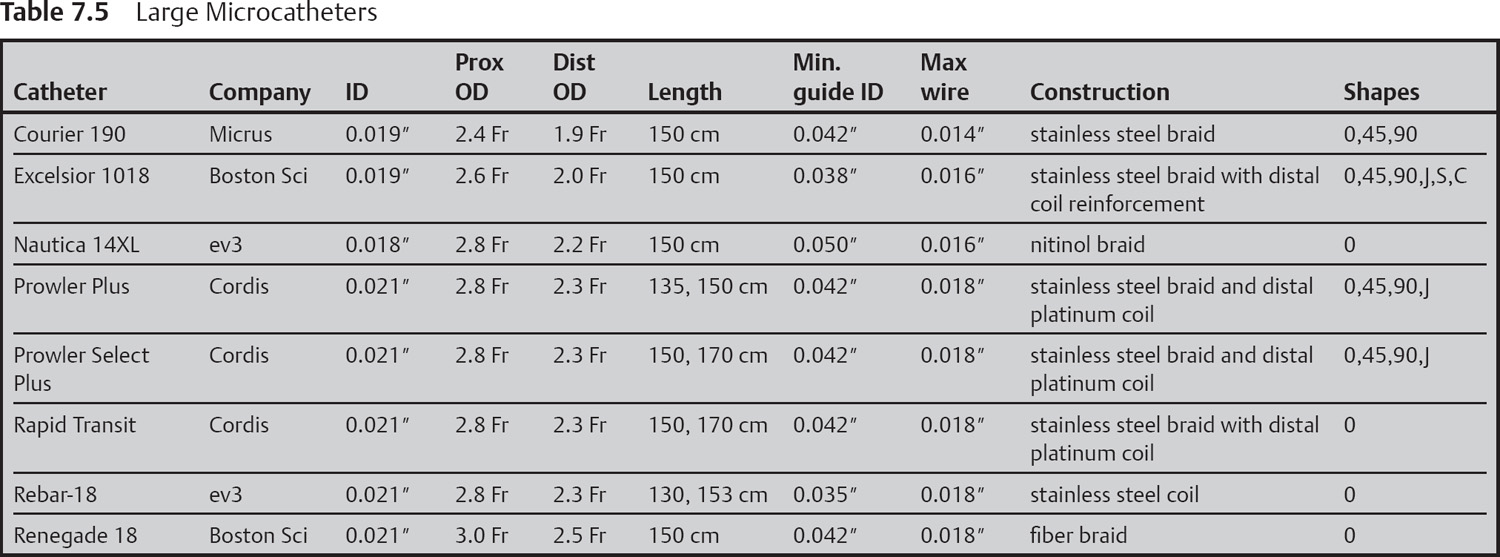
Large Microcatheters (Table 7.5)
• They have a tip diameter between 2.0 and 3.0 French.
• They are large enough to accommodate intracranial stents, large embolic particles, and large aneurysm coils.
• Like the medium-sized catheters, large catheters have a reinforcing metal braid or coil to make them easy to advance over a wire and more burst resistant.
• They are used for intracranial stent delivery, large particulate delivery, mechanical thrombolysis, and deploying large coils.
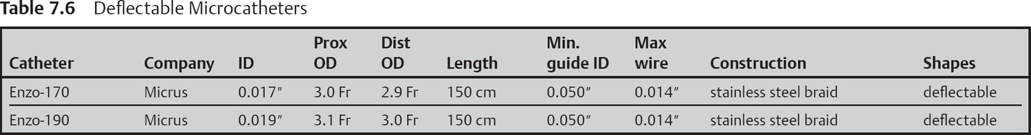
Deflectable Microcatheters
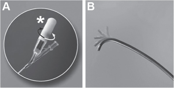
The Courier Enzo (Micrus) has a deflectable tip that can be directly controlled from outside the patient. Deflection is accomplished with two microcontrol wires that are mechanically linked to a knob in the hub of the catheter. Turning the knob pulls on one of the wires, causing the tip to curl in one direction or the other (Fig. 7.11).
The additional mechanical components do add some bulk to the catheter (Table 7.6). The outer diameter of the smallest tip for the Enzo is 2.9 Fr, with a working lumen of 0.017″. By comparison, the Echelon 10 (ev3) achieves the same working lumen with a 1.9 Fr tip.
Microcatheter Shaping
• A small malleable metal stylette is inserted into the tip of the microcatheter.
• The microcatheter is bent into the desired shape around the stylette.
• The tip of the microcatheter is held in steam for 30–90 seconds.
• Saline is used to cool the tip prior to removing the stylette.
• Alternatively, the microcatheter can be shaped by very gently bending or running the tip of the microcatheter between the thumb and over a stiff metal stylette. Meticulous care must be taken to not collapse the inner lumen of the microcatheter. A stylette is normally provided with the microcatheter that is inserted into the lumen at the time of shaping.
Wires
Guidewires
Guidewires are wires used to select pre-cerebral vessels off the aortic arch. In most cases a regular stiffness 0.035″ angled wire is stiff enough to exhibit good torque and navigational control but gentle enough to be safe in the high cervical vessels. Stiff guide wires can be useful in tortuous anatomy or when pushing stiff guide sheaths/catheters such as the Cook Shuttle (Cook, USA). Hydrophilic wires tend to be easier to push and steer, particularly when used with a torque device (Fig. 7.12). Consider a non-hydrophilic wire for difficult exchanges to prevent the wire from slipping out of position.
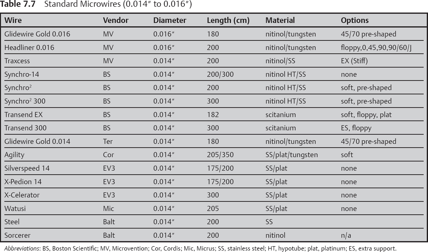
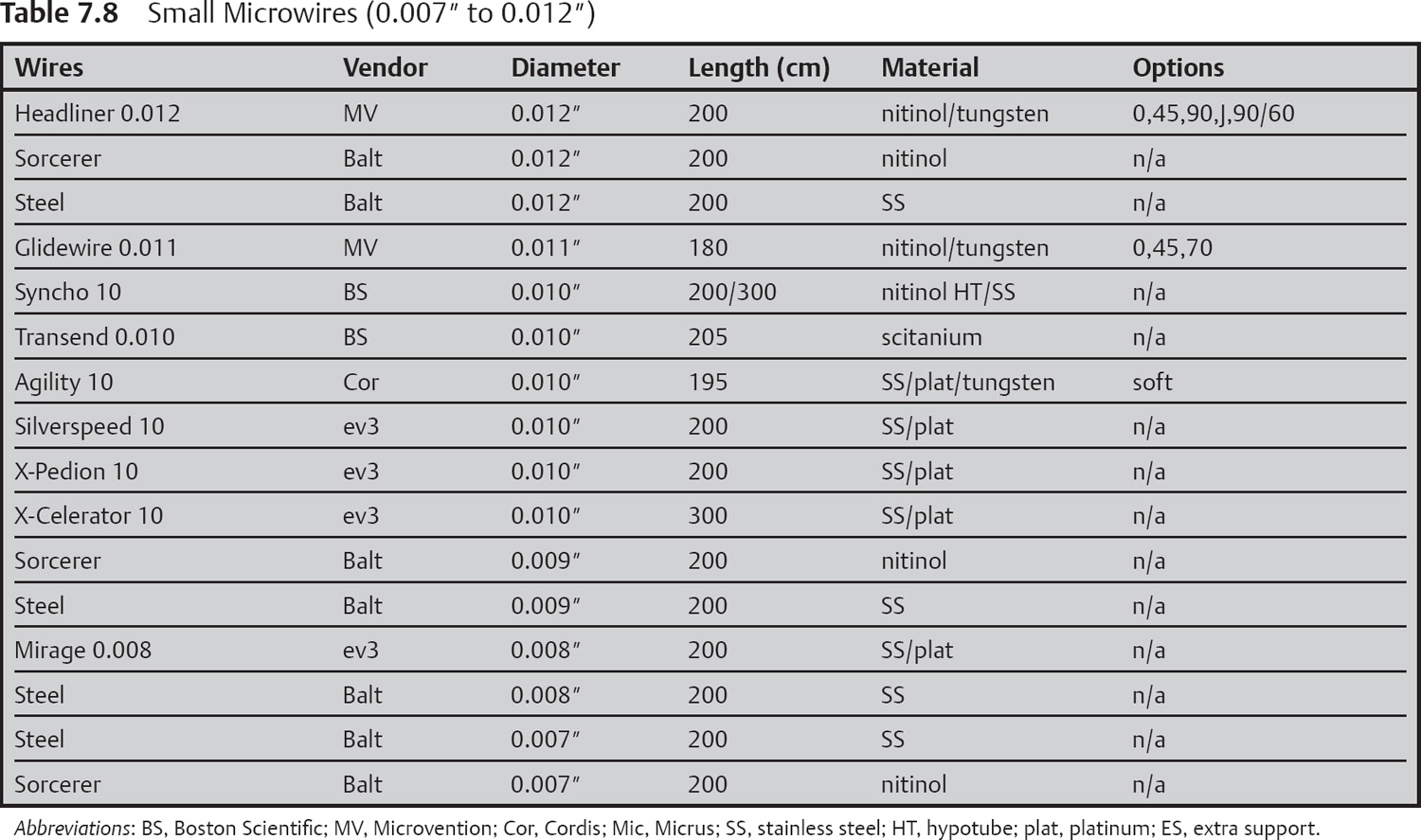
Microwires (Tables 7.7 and 7.8)
Microwires (with diameters from 0.007 inch to 0.021 inch) are used to steer microcatheters, balloons, stents, and other devices into distal pre-cerebral and intracranial vessels. All wires have soft tips that can be shaped on the table. Pre-shaped wires are also available from some manufacturers. Construction materials vary between manufacturers and include stainless steel, platinum, nitinol, and proprietary alloys. Each material confers subtle, subjective, unique handling properties.
Recommendations for Choosing a Microwire
• Most of the devices used for neurointerventional procedures are designed for use with a 0.014 inch microwire. Some notable exceptions include hyper-balloons and some flow-guided microcatheters used for AVM embolization.
• Larger microwires (0.016 inch, 0.018 inch, or 0.021 inch) may help to straighten out tortuous anatomy or to manipulate through occluded vessels.
• Care must be taken when small microwires are used. They can be difficult to see and do not provide good support while passing devices.
• Choose one or two wires in each size and get to know them well rather than trying a new wire for every case. The differences between similarly sized wires are subtle and subjective.
• Nitinol wires generally have better torque control than platinum or stainless steel wires.
Balloons
Balloons used for neuroendovascular procedures can be divided into two categories, compliant and noncompliant. A compliant balloon is a soft, low-pressure balloon that conforms to the vessel wall as it is inflated. Compliant balloons are useful for temporary vessel occlusion and balloon-assisted aneurysm coiling because they are gentle on vessel walls. Noncompliant balloons, conversely, are stiffer balloons that attain a particular size and shape at a given pressure. These balloons will force the vessel to conform to their shape, making them better suited for angioplasty.
Compliant Balloons
Related posts:

Stay updated, free articles. Join our Telegram channel

Full access? Get Clinical Tree


