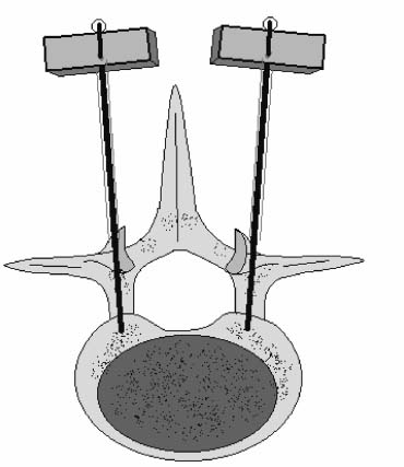
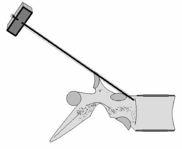
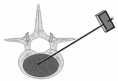
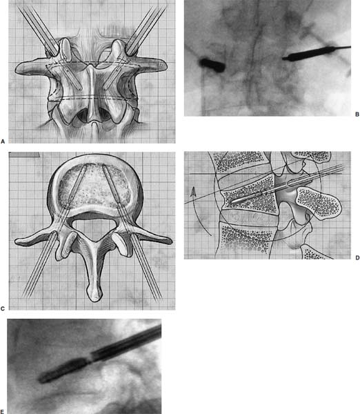
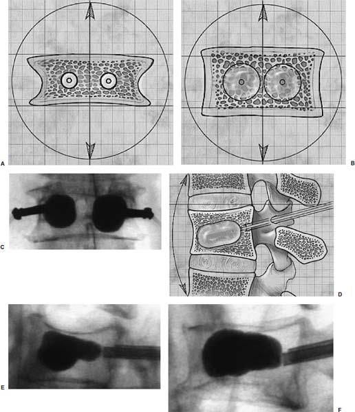
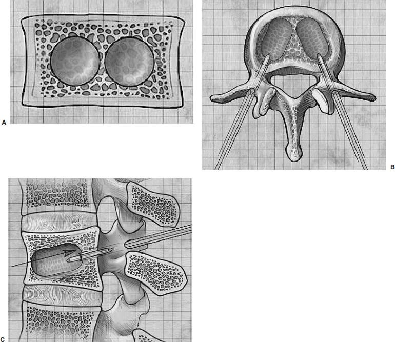
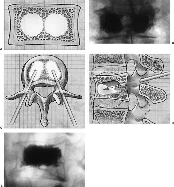
Methods of reduction and internal stabilization of spine fractures typically require extensive open procedures. With a growing demand for minimally invasive methods, an interest in percutaneous techniques of fracture reduction and fixation has arisen. Kyphoplasty has been developed for the treatment of painful osteoporotic compression fractures of the thoracic and lumbar spine. Using an inflatable balloon tamp inserted into the vertebral body, anterior height loss in a compressed segment can be restored and maintained with the insertion of methacrylate cement.1,2 This technique offers a unique option to patients who would otherwise be managed with prolonged nonoperative care or by extensive open anteroposterior surgery.3–5 Fractures at multiple levels can result in progressive anterior column shortening and thoracolumbar kyphosis. This can potentiate disability, lung dysfunction, and eating disorders by decreasing thoracic and abdominal volumes, especially in the elderly.6–9 Because of this, interest in a minimally invasive method of kyphosis correction has gained attention. Preliminary clinical data indicate consistent restoration of vertebral height in addition to durable pain relief in 90% of cases with low complication rates.1,10 Kyphoplasty is not limited to the treatment of osteoporotic vertebral compression fractures (VCFs). It has been used to stabilize pathologic fractures secondary to multiple myeloma, and it may be indicated for metastatic tumors as well.11–13 With continuing advances in bioresorbable materials, the procedure will likely have a place in the future treatment of traumatic vertebral fractures in normal bone. Indications The clinical indications of kyphoplasty are (1) treatment of painful osteoporotic VCFs, (2) restoration of height loss and correction of kyphosis secondary to VCFs, and (3) pain relief from neoplastic lytic bone lesions that do not require excision. The primary indication for kyphoplasty is the relief of pain related to osteoporotic VCFs. Although deformity correction (i.e., vertebral height restoration) is achievable in more acute fractures, it should be considered a secondary benefit. A patient with a nonpainful, static deformity associated with osteoporotic VCFs should not be considered an operative candidate unless kyphosis is rapidly progressive. In most cases, however, this is associated with intractable pain. Vertebral augmentation, either kyphoplasty or vertebroplasty, can relieve pain in more than 90% of patients treated.1,14–16 The most likely mechanism of pain relief is fracture stabilization, although some experts believe the exothermic effects of methacrylate curing can “denervate” the vertebral body. Optimal results with kyphoplasty rely on a careful physical examination and correlative imaging studies to identify the most symptomatic level(s). Systematic percussion of the spinous processes can localize pain to a particular level, which can then be marked with a radiopaque marker before plain radiographs are made. This information should be considered along with results of MRI of the spine, which can display increased T2 signal in acutely fractured vertebrae.17 STIR images are helpful in differentiating fracture from tumor, which may be difficult based on plain films and clinical history alone. If MRI is not possible, a CT and bone scan can be used as an alternative to determine the most acute level.18 Osteoporotic Kyphosis Kyphoplasty is a deformity-correcting procedure; however, the presence of a compressed vertebral body is not an automatic indication for kyphoplasty. Spinal balance must be considered, as with other deformity operations. Because the osteoporotic spine is usually rigid, bending films are of limited utility. Long plate anteroposterior and lateral views are essential in evaluating the location of the weight-bearing line. In older fractures, kyphoplasty may have minimal effects on correcting balance, whereas acute fractures are more amenable to restoration. Further investigation is required to demonstrate a positive balance between the potential benefits of kyphosis correction versus procedural risks more clearly. Kyphosis is quantitated using the Cobb method. Extrapolating from recommendations for Scheuermann’s disease, correction might be warranted for curves of 75 to 80 degrees or those that do not correct to less than 50 degrees. Considering the percutaneous nature of kyphoplasty with minimal morbidity, smaller curves might be considered if spinal balance is compromised. Fracture risk increases after an intitial VCF.19–21 The surgeon must consider the projected amount of kyphosis that the patient is likely to exhibit in his or her lifetime. Furthermore, rigid deformities from multiple healed fractures might be better addressed by other procedures. Restoring spinal balance may help reduce fracture risk, although this remains to be demonstrated in a prospective clinical investigation. VCFs and kyphosis can negatively affect pulmonary function, especially in the elderly patient.9,22 Schlaich et al9 demonstrated a strong correlation between the severity of kyphosis and compromise of measured lung capacity. In addition, mortality rates associated with pulmonary complications are significantly higher in patients with kyphotic VCFs than they are in those without deformity.22 Such procedures as kyphoplasty that can either arrest or correct kyphosis secondary to osteoporotic VCFs would therefore be useful. Further study to determine if deformity correction can reverse these negative effects is required. Lytic Bone Tumors Kyphoplasty is indicated in the management of pain associated with lytic lesions of the vertebral body secondary to neoplastic processes. Experience treating multiple myeloma lesions in the spine has been encouraging.13 The procedure may also be involved in the treatment of metastatic tumors. The best results can be expected when one or two symptomatic lesions can be localized in patients without neurologic compromise. Preoperative imaging should confirm that the posterior vertebral body is not disrupted to avoid cement extrusion or balloon tamp blowout into the spinal canal. Contraindications Kyphoplasty should not be performed in stable, healed, painless fractures. Bleeding abnormalities, either intrinsic or pharmacologic, must be corrected preoperatively to avoid epidural hematoma formation, particularly if the pedicle cortex or posterior vertebral body has been penetrated. Although we do not routinely perform kyphoplasty on osteoporotic burst fractures because of concern of posterior cement extrusion, it may have a role in select cases with minimal to no canal compromise in a neurologically intact patient. Other fracture patterns, (e.g., vertebra plana) make it difficult or impossible to cannulate the vertebral body. Operating Room Setup Both general and local anesthesia can be used. It is the authors’ preference to use general anesthesia for patients undergoing multilevel procedures. Local with sedation is suitable for one-segment procedures with the advantage of the ability to monitor neurologic status intraoperatively. The disadvantage of local anesthesia is discomfort sometimes experienced during cannulation of the pedicle and the need for the awake patient, who is often elderly, to remain absolutely still throughout the procedure. With either anesthesia type, the patient is positioned prone on a radiolucent table, carefully protecting all pressure points. Transverse rolls under the chest and thighs help extend the spine and fracture reduction. A radiolucent Jackson table or a Kambin frame can be used as an alternative. For work at the L1 level and above, the arms should be tucked at the sides to allow access for the image intensifier (C-arm). Before starting the procedure, it is imperative that an adequate lateral can be obtained because the arms can sometimes obscure the view of the spine. One or two C-arms can be used. If two machines are used, they must be adjusted so that the PA and lateral views can be taken at the same time (Fig. 30–1). The PA machine must be raised up enough to allow the surgeon ample room to place the instruments. A single C-arm can be used successfully, but it requires frequent moves to see both the posteroanterior (PA) and the lateral images. The PA view should be adjusted so that the pedicle “halo” is clearly seen. Although this is more easily afforded on a PA view in the thoracic spine, medial pedicle angulation in the lumbar spine may be better seen with the “en face” view. This is achieved by angling the beam 10 degrees toward the midline. During each step of pedicle cannulation, the instruments should be perfectly centered within the pedicle on the en face view. Once adequate radiographic visualization is confirmed, the patient is prepped and draped in the usual sterile fashion. FIGURE 30–1 Two C-arms are optimally used. This allows simultaneous PA and lateral fluoroscopic views. Surgical Technique Transpedicular Approach The most often used approach for kyphoplasty, the transpedicular approach, can be used from T8 to L5 and requires a pedicle diameter of at least 4 to 5 mm (Fig. 30–2). In the upper thoracic spine, the pedicles usually are too thin to safely accept the instruments, making other approaches (extrapedicular, see later) a better choice. This determination should be made preoperatively based on CT or MRI axial image measurement. Structures endangered using the transpedicular technique are the spinal cord or cauda equina medially, the nerve root superiorly and inferiorly, and in the thoracic spine the pulmonary cavity laterally. If the anterior vertebral body is violated, which may occur in any of the three approaches, the great vessels may be injured. The midline is marked by palpation, and the correct vertebral level is identified using the C-arm. Using the PA view, a Jamshidi needle or guide pin is introduced through the skin just lateral to the lateral pedicle border. The instrument is advanced to the bone at approximately a 10–degree angle toward the midline. Once the bone can be felt with the needle, orthogonal images confirm proper orientation. On the lateral it should be aligned with the midline of the pedicle. On the PA view, it should appear to be just medial to the lateral border of the pedicle halo, remembering that the halo represents the pedicle waist, which is anterior and medial to the point of needle entry. The needle tip should be within the confines of the pedicle at all times. FIGURE 30–2 The transpedicular technique is the most commonly used approach. The appropriate starting point is crucial. With this confirmed, the instrument is advanced through the pedicle and into the vertebral body. In severely osteoporotic patients, this can be difficult to discern because of poor bone quality, making frequent C-arm images necessary. The Jamshidi is advanced to just beyond the junction of the vertebral body and pedicle. In this position, the needle may appear medial to the pedicle on the PA view. Although this appearance is acceptable, the tip should not cross the midline on this view at any point during insertion. If it does, the surgeon must try to determine if the medial pedicle cortex has been breached. If doubt exists, the instrument should be repositioned until safe placement is confirmed. Because the instruments’ diameters are generally smaller than the pedicle dimensions, they may be slightly cranially or caudally directed to target a particular region of the fractured vertebra. For instance, the device is directed toward the inferior vertebral body in a superior end-plate fracture. This places more cancellous bone between the inflatable tamp and the injured end plate. With uniform vertebral body compression, the tools are directed toward the midaspect. FIGURE 30–3 The extrapedicular approach utilizes the interval between the rib and the pedicle. Optimal placement is obtained by starting at the posterosuperior aspect of the vertebral body, aiming for the anteroinferior aspect. Extrapedicular Approach The extrapedicular approach should be used in thoracic vertebrae with pedicles too small to accept the kyphoplasty tools. Because it employs the interval between the pedicle and the rib, it is not an option in the lumbar spine. Under C-arm guidance, the Jamshidi needle is inserted just lateral and superior to the pedicle on the PA view (Fig. 30–3). On the lateral view, it should be centered within the pedicle, although anatomically it will be lateral to it. On the PA view, the needle should appear to enter the bone at the superolateral aspect of the vertebral body, aiming inferomedially (~20 degrees) toward the spinous process. On the lateral view, it is directed toward the anteroinferior aspect of the vertebral body. The spinal cord is at less risk with a more lateral starting position than the transpedicular approach, although it may still be injured with medial misplacement. Lateral deviation risks pneumothorax, which may not be detected until high-quality postoperative plain radiographs are taken. Lateral vertebral body violation can injure the segmental artery, great vessels, or lungs. Posterolateral Approach The posterolateral approach for kyphoplasty can be used in the L2 to L4 vertebrae. The bone is entered through the posterolateral cortex, anterior to the transverse process. Although the transpedicular and lateral extrapedicular approaches can be used bilaterally, the posterolateral technique is a unilateral approach. The needle trajectory is similar to that for a diskogram, except that it is aligned with the vertebral body instead of the disk (Fig. 30–4). Skin entry is 8 to 10 cm lateral to the midline, with the needle directed ~45 degrees toward the midline. The PA view should confirm that the needle is confined to the borders of the vertebral body, optimally positioned within the center of the bone. The lateral view ensures that the needle tip does not pass anterior or posterior to the vertebral body, which can have disastrous sequelae. With proper placement, the instruments pass anterior to the transverse process and the neural foramen, avoiding injury to the exiting nerve root. Dangers encountered with this approach include injury to the nerve root if the needle is not anterior to the transverse process. Anterior or posterior migration can injure the great vessels or cauda equina, respectively. Passage of the instruments through the psoas muscle can injure components of the lumbar plexus. It is best if the patient is awake during this technique to help avoid transecting the nerve roots because the patient can vocalize leg pain during the procedure. FIGURE 30–4 The PA technique utilizes a “diskogram” type of approach aimed toward the midportion of the vertebral body. It risks injury to the segmental vessel and the exiting nerve roots. Bone Tamp Insertion The center stylet of the Jamshidi needle is removed, and a flexible guidewire is inserted. Holding the guidewire in place, the Jamshidi is removed from the body. C-arm images should confirm maintenance of wire orientation. An initial dilator is passed over the guidewire and advanced to the junction of the vertebral body and pedicle. This must be performed with frequent lateral images because the guidewire can be inadvertently advanced through the anterior cortex. Next, a working cannula is inserted over the dilator. The dilator and guidewire can then be removed. A finger twist drill is inserted through the cannula and advanced incrementally to the anterior vertebral body cortex. We must warn that, as the bone is soft, this must be performed under radiographic guidance to avoid penetration of the cortex. FIGURE 30–5 Illustrative and radiographic views of the optimal positioning of the instruments and the balloon tamp. (A) The PA view confirms that the instruments are within the “halo” of the pedicle. (B) Note that the tamp is aimed toward the midline (C) and the anterointerior edge of the vertebral body (D,E). FIGURE 30–6 The balloon is sequentially inflated until the fracture is reduced. Inflation is stopped if pressures become too high (greater than 350 psi) or breakout beyond the vertebral body cortex appears imminent. Artist’s depiction of the vertebral body (A) before and (B) after inflation of the balloons. (C) AP fluoroscopy of balloon inflation. (D) Lateral depiction of balloon inflation. (E, F) Lateral fluoroscopy during inflation. The twist drill is removed. Small pieces of bone within the flutes of the drill can be sent for microscopic analysis, if warranted. Next, the inflatable balloon tamp (Kyphon, Inc., Santa Clara, CA) is inserted through the cannula (Fig. 30–5). The surgeon must choose between a small (15 mm) or large (20 mm) balloon. This can be determined preoperatively using CT or MRI measurements. Upper and middle thoracic vertebrae can often accommodate only a small balloon tamp, whereas lower thoracic and lumbar vertebrae may accept the larger one. FIGURE 30–7 The balloon tamp creates a void within the soft cancellous bone of the osteoporotic vertebral body. This facilitates low-pressure injection of cement. (A) Anteroposterior, (B) axial, and (C) sagittal images. Instead of being a concentric sphere, the tamp is slightly narrowed in its midpoint, creating “anterior and posterior” tamps. Though not a flat surface, this facilitates better “en masse” reduction of the fractured end plate. The anterior and posterior limits of the tamp are delineated with small radiopaque markers. Because the tamp itself is radiolucent, this facilitates proper positioning within the vertebral body before inflation. The balloon is then inflated under controlled pressure, using a digital manometer, with a radiopaque contrast liquid. Fracture reduction and tamp location are judged on both the PA and lateral C-arm views (Fig. 30–6). In addition to height restoration, the surgeon must ensure that the balloon is maintained within the limits of the bone. Small “blebs” of the balloon can puncture through the superior or inferior end plates that may allow cement leakage. The lateral wall may also be “blown out” if care is not taken. Overinflation can risk spinal canal violation. In acute fractures treated within 2 to 3 months, up to 99% of predicted height can be restored. The correction is not as reliable with older fractures. FIGURE 30–8 Cement is inserted in 1.5 ml increments using bone filler devices. This is monitored with frequent fluoroscopic images to ensure that the cement remains within the vertebral body. Cement injection is stopped once material has reached the posterior aspect of the vertebral body/anterior aspect of the pedicle or if cement appears to be leaking. In most cases, cement extravasation is clinically insignificant. (A) AP artist’s depiction and (B) fluoroscopy. (C) Axial and (D) sagittal depiction with (E) lateral fluoroscopy after PMMA injection. Cement Composition The use of polymethyl methacrylate (PMMA) in the spine is considered “off label” use. Regardless, it is currently the only accepted material for vertebral body augmentation in humans. To increase its radiopacity, 6.0 g of barium sulfate are added to each 40 ml bag of cement, as well as 1.0 g of a heat-stable antibiotic powder (i.e., cefazolin, vancomycin, or tobramycin). The dry substances are mixed thoroughly before adding 10 ml of the liquid monomer. The combination is then blended until homogeneous. Although still liquid, the cement is injected into long tubular bone-filler devices. These fit snugly into the working cannula. The cement is allowed to cure to a much more viscous state than required for vertebroplasty. The cement is ready for injection when a long bead of cement can be suspended from the tip of a syringe. Cement Delivery The balloons are deflated (Fig. 30–7). Bone-filler devices are inserted into both cannulas. A central pusher is used to deliver the cement into the bone, which is carefully monitored using the C-arm. In unstable fractures, the contralateral tamp can be kept inflated to maintain reduction while cement is injected through the ipsilateral side. Cement injection is continued until cement (1) has filled the anterior two thirds of the vertebral body, (2) begins leaking through the vertebral body, or (3) starts to fill the posterior aspect of the body (Fig. 30–8). If the cement is too liquid, it may leak through small cracks in the vertebra walls or end plates. In this case, injection can be temporarily stopped, allowing the peripheral cement to begin to cure and seal any potential leaks. Depending on the volumes achieved during tamp inflation, 2 to 6 ml of cement can be injected on each side. The cement is allowed to cure for 5 to 10 minutes. After hardening, the instruments are twisted and carefully removed. Final images are taken to confirm cement placement, fracture reduction, and restoration of alignment. Complications Few complications have been reported with kyphoplasty. In an ongoing multicenter study,1 clinical complications occurred in 1.2% of patients and 0.7% of fractures. The most common technical complication is cement leakage, which may be as high as 8.6%, although this is rarely associated with clinically detectable sequelae. Neurologic injury has unfortunately been reported secondary to cement extrusion into the canal or neural foramina.1,23,24 These complications do not appear to be related to the use of the balloon tamp per se, but were more likely secondary to original, improper Jamshidi needle placement. The most common clinical complication of vertebral augmentation is transient pyrexia, probably from a mild systemic reaction to the PMMA, and appears to be more frequent after vertebroplasty than kyphoplasty. Intraoperative hypotension has been reported during cement injection with vertebroplasty, although this has not been reported during kyphoplasty. Other potential complications are epidural hematomas, which are more likely with anticoagulant administration, and pneumothorax, if instruments are inserted too lateral in the thoracic spine. For safety, anticoagulants should be stopped 1 week before surgery and reinitiated no earlier than 4 days postoperatively. If anticoagulation cannot be stopped for risk of a massive thromboembolic pulmonary event, placement of an inferior vena cava filter before kyphoplasty should be considered. REFERENCES 5. Hu SS. Internal fixation in the osteoporotic spine. Spine. 1997;22:43S–48S. 11. Heary RF, Bono CM. Metastatic spine tumors. Neurosurg Focus. 2001;11:1–9. 15. Jensen ME, Dion JE. Percutaneous vertebroplasty in the treatment of osteoporotic compression fractures. Neuroimaging Clin N Am. 2000;10:547–568. 16. Jensen ME, Dion JE. Vertebroplasty relieves osteoporosis pain. Diagn Imaging. 1997;19:68,71–72.
30

Kyphoplasty

< div class='tao-gold-member'>
Related posts:
 Endoscopic-Assisted Transoral Odontoidectomy
 Endoscopic Lateral Transpsoas Lumbar Spine Fusion
 Combined Prone Position Thoracoscopic Anterior Release and Posterior Instrumentation for Deformity Surgery
 Anterior Endoscopic Cervical Microdiskectomy
 Nucleoplasty
 Minimally Invasive Instrumentation, Correction, and Fusion of Primary Thoracic and Thoracolumbar Scoliosis


