54 Percutaneous Pedicle Screw Placement
I. Key Points
– Numerous methods can be used for implanting percutaneous pedicle screws, such as image guidance, en face targeting, and biplanar fluoroscopy.
– Percutaneous screws can be safely placed in the thoracolumbar spine using a simple method based primarily on anteroposterior (AP) x-rays.
– Percutaneous screw-rod constructs are a truly minimally invasive surgical (MIS) technique for segmental fixation.
II. Indications
Percutaneous placement of transpedicular screws with connecting rods can find application in virtually any setting where open screw fixation might be utilized in the thoracolumar spine. For a fusion setting, this can be employed in conjunction with interbody fusion for stabilization,1 such as after an anterior lumbar inter-body fusion (ALIF), lateral interbody fusion, transforaminal lumbar interbody fusion (TLIF), or transsacral fusion. In addition, a speculum retractor can be used to expose the lateral masses for posterolateral fusion bed preparation in conjunction with percutaneous fixation. Also, percutaneous fixation can be used for stabilization or “internal bracing” in the absence of a bony arthrodesis.2 Thus, whether a fusion is intended or not, percutaneous screwrod fixation can be used to confer spinal stability for degenerative, traumatic, neoplastic, and infectious pathologies.
III. Technique
There are various methods for targeting the pedicles of the lumbar or thoracic spine. These include (1) frame-based or frameless image-guided navigation,3(2) biplanar fluoroscopy in the AP and lateral views, (3) “en face” or “direct down the pedicle” imaging,4(4) a mini-open technique with tactile feedback, and (5) an AP-based targeting method.5 This chapter will describe the AP-based targeting method.
– 1. The patient is positioned prone on a radiolucent operating table. Care is taken to ensure that there are no obstructions to the fluoroscopic image at the level(s) of interest, as the technique is heavily dependent on intraoperative imaging.
– 2. An absolutely precise AP view is registered at the level of screw placement. This is done by first ensuring that the axial rotation of the fluoroscope aligns the spinous process equidistant between the right and left pedicles (Fig. 54.1). Either the fluoroscope can be moved or the bed rotated to register this image, but the surgeon must compensate for any rotation depending on the method used. The sagittal (Ferguson) angle is then adjusted so that the anterior and posterior cortical rims of the upper end plate of the vertebral body are superimposed into a single line. This ensures that the x-ray beam is completely aligned with the sagittal plane of the pedicles (and thus an ideal screw trajectory).
– 3. The skin is then marked so that a cutaneous entry point can be made 1 to 2 cm lateral to the lateral border of the pedicle. A Jamshidi needle (MedSurge, Chennai, India) is then inserted through the skin and directed slightly medially to contact the bone surface. The needle is then docked at the junction of the transverse process and facet joint near the mamillary process (the attachment of the multifidus muscle).
– 4. Once the Jamshidi needle has been docked on this ideal pedicle screw starting point, the needle is marked 2 cm above the skin surface with a surgical marker (Fig. 54.2). The needle is then hammered into the pedicle to a depth of 2 cm (where the marking meets the skin surface). The trajectory will be medialized to match the patient’s anatomy (10 to 30 degrees). If a proper AP image has been obtained, making the Jamshidi needle parallel to the horizon and parallel to the upper end plate will place the needle in the proper sagittal orientation.
– 5. So long as the medial wall of the pedicle is not breached at a depth of 2 cm, there will be no medial pedicle wall violation; the needle will have passed the depth of the pedicle (and spinal canal) following 2 cm of advancement. Once the Jamshidi needle has been placed, the inner stylet is removed and a Kirschner wire (K-wire) is inserted into the vertebral body.
– 6. The procedure is then conducted at other vertebral levels with adjustments in fluoroscopic targeting for each level. After all of the K-wires have been placed, the fluoroscope is moved to a lateral position. The K-wires are then used to guide an awl and tap for pedicle preparation as with open surgery. Final pedicle screw placement is then performed followed by K-wire removal.
– 7. During the procedure, care is taken to ensure that the K-wires do not violate the anterior vertebral body and enter the retroperitoneum, which could cause vascular or hollow viscus injury. In addition, care must be taken not to lose control of the wires or have them pull out prematurely.
– 8. Following screw placement a percutaneous rod is advanced subfascially through the screw extensions to connect the segmental levels (Fig. 54.3). Rod insertion can occur through one of the end screw incisions or through a separate incision distal to the screws.
– 9. It is helpful to have at least some bend in the rod, as “steering” the rod medially or laterally is made easier by rotating the rod along its long axis to turn the tip medially or laterally. Finally, set screws are placed through the screw extensions to lock the rod to the individual screws.
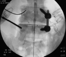
Fig. 54.1 AP projection on the L5 vertebral body. Note that the upper end plate of the L5 body is visualized as a single line and that the spinous process is equidistant between the two pedicles.
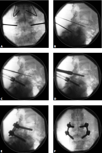
Fig. 54.2 (A) AP view targeting the lower vertebral body. Note the rotation in relation to the body above (where the spinous process is not in the midline). Docking at the junction of the facet joint and transverse process is followed by 2 cm of medial needle advancement. (B) The needle is confirmed on lateral fluoroscopy as having passed the spinal canal, ruling out pedicle wall violation. (C) An insulating sheath is used to minimize soft-tissue trauma while an awl and tap are advanced over the K-wire. (D) Final screw positioning with extension tabs attached to guide rod insertion. Final construct as visualized on (E) lateral and (F) AP views.
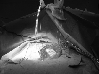
Fig. 54.3 Jamshidi needles and K-wires in place. Note the use of a long skin incision with placement of instrumentation through the exposed fascia and the use of a needle driver to control the K-wire during manipulation.
IV. Complications
The complications associated with percutaneous screw placement are akin to those encountered with open surgical instrumentation procedures. In addition, there are risks associated with loss of control of the K-wires, which can result in inadvertent entry into the retroperitoneum.
Difficulties can be encountered with initial pedicle cannulation or with rod passage and screw-rod connection. Use of the AP-based technique results in a low rate of pedicle violation as long as high-quality fluoroscopic images are utilized for targeting the Jamshidi needles. Rod passage and connection techniques are often specific to the implant manufacturers and the instruments available for rod and screw manipulation, so they are not described here.
V. Postoperative Care
Care after surgery is the same as with open instrumentation. Patients should be rapidly mobilized with physical therapists, with external bracing as a treatment option. Muscle spasm occurs more commonly with MIS procedures and is best treated with muscle relaxants and benzodiazepines as opposed to narcotics.
VI. Surgical Pearls
– In many instances all of the surgery can be accomplished by a single surgeon standing on the side opposite the fluoroscope. This improves surgical workflow and minimizes the risk of contaminating the sterile field. Because of the highly imaging-dependent nature of the method described here, standing on the same side as the pedicle screw insertion (which is typical for open surgery) is much less important.
– When a rod is passed across the thoracolumbar junction it is usually preferable to pass the rod from cranial to caudal.
– Because the screw head heights and orientation are not immediately visible, the surgeon should be prepared to pass a prepared rod initially, and then remove it and recontour or resize the implant to achieve the optimal construct. Forcing the screw and rod to mate may result in screw pullout.
Common Clinical Questions
1. Percutaneous pedicle screws can be safely inserted using all of the following techniques except:
A. AP-guided imaging
B. Pure freehand technique
C. Biplanar fluoroscopy
D. Image guidance
2. When using the AP-based technique for percutaneous pedicle cannulation, how far is the Jamshidi needle advanced before passing the medial pedicle wall?
A. 1 cm
B. 2 cm
C. 3 cm
D. 4 cm
3. Bending the rod allows what to be accomplished more easily?
A. Cutting the rod to size
B. Reducing spondylolistheses
C. Rod-screw mating
D. Medial and lateral maneuvering
Related posts:


Stay updated, free articles. Join our Telegram channel

Full access? Get Clinical Tree


