CHAPTER 301 Posterior Thoracic Instrumentation
Anatomy and Biomechanics
The musculature overlying the dorsal surface of the thoracic spine contributes to the maintenance of sagittal and coronal balance and aids in controlling rotation. The dorsal musculature can be roughly divided into superficial and deep layers. Proper exposure for placement of thoracic instrumentation often requires visualization of the facets, transverse processes, and sometimes the ribs through extensive, careful muscle dissection. Using fascial planes and subperiosteal dissection reduces blood loss, postoperative pain, and wound complications. Rotation and transposition of muscle flaps can also be a useful adjunct to provide coverage for spinal hardware and promote wound healing in patients with poor healing potential, previous radiation, or revision surgery.1
It cannot be overstated that there is considerable individual variability with regard to the dimensions and angulation of the thoracic pedicles, making it generally advisable to assess pedicular anatomy with preoperative radiographic evaluation before attempting transpedicular fixation.2–4
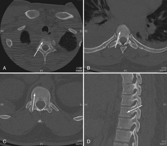
In general, the pedicular dimensions are larger in men.5,6 The width of the pedicle decreases from T1 to T4 and then gradually increases to T12, whereas the pedicle height and length tend to increase from T1 to T12. The transverse angle of the pedicle, however, decreases from T1 to T12, such that the pedicles become less medially inclined the closer they are to the thoracolumbar junction. At T1 and T2, the pedicles have a medial projection of 30 to 40 degrees; at T3 to T11, this transverse angle is about 20 to 25 degrees; and at T12, the transverse angle is closer to 10 degrees (Fig. 301-1).3–8 Conversely, the pedicular sagittal angle remains consistent throughout the thoracic spine (downward projection of about 10 to 20 degrees) (see Fig. 301-1D). Most of the pedicle is composed of cancellous bone, which is encased in a shell of cortical bone, that is significantly thicker medially than laterally. This may account for the finding that most screw-related pedicle fractures occur laterally.9,10

FIGURE 301-1 Axial plane pedicle angulation at T1 (A), T7 (B), and T12 (C). D, Representative sagittal pedicle angulation.
The thecal sac abuts the medial wall of the pedicle, and the nerve root exits under the inferior wall of the same numbered pedicle. The nerve roots tend to have a more cephalad angulation and a closer relationship to the pedicle in the upper thoracic spine and a more caudal angulation with a greater distance from the pedicle in the lower thoracic spine.5 The thoracic facets are oriented in a coronal plane throughout most of the thoracic spine (T1 to T10). This orientation provides stability against anteroposterior translation. In the lower thoracic spine, the facets take on a more sagittal orientation, providing more stability against rotation. The spinous processes project inferiorly in the upper and middle thoracic spine but have a more horizontal configuration in the lower thoracic spine.
The spinal ligaments and joint capsules preserve the articulated nature of the spine, allowing a requisite but restrained amount of movement. The anterior longitudinal ligament contains a relatively higher proportion of collagen and acts to prevent hyperextension and overdistraction.11 Testing has found that the strength of the anterior longitudinal ligament increases as it descends toward the thoracolumbar junction.12 The posterior longitudinal ligament functions to limit hyperflexion of the spine. Its tensile strength is about half that of the anterior longitudinal ligament. The integrity of the posterior longitudinal ligament is essential when attempting to perform indirect reductions of fractures through ligamentotaxis with posterior instrumentation.13
Biomechanics
Whitesides defined a stable spine as one that possesses sufficient integrity to protect the neural elements from initial or subsequent damage and prevent the development of incapacitation deformity and severe pain under physiologic loads.14 Proper instrumentation warrants a thorough understanding of the unique biomechanical considerations in the thoracic region. In general, the thoracic spine is a relatively less mobile segment positioned between two regions of relatively abrupt motion transition zones at the cervicothoracic and thoracolumbar junctions. This transition between relative mobility and immobility makes cervicothoracic and thoracolumbar junctions more susceptible to traumatic injury and destabilization. The thoracic spine has a normal kyphosis over its length (20% to 45%, increases with age) but is relatively neutral across the thoracolumbar junction.11,15 This kyphosis makes the thoracic spine more susceptible to sagittal imbalance and instability. This kyphosis is formed in utero and is maintained by the differences in the anterior and posterior vertebral bodies and disk dimensions. The height of the ventral surface of the thoracic vertebral body is about 1 to 2 mm less than that of the dorsal surface. This slight height difference is also seen in the thoracic intervertebral disks.16
Similar to other regions of the spine, the vertebral bodies support most of the axial loading forces, and the intervertebral disk complexes are major stabilizers of the thoracic spine. Additionally, the steep orientation of the facets limits sagittal translation. However, the rib cage and sternum provide significant inherent stability to the thoracic spine in flexion-extension, lateral bending, and axial rotation.17 Sternal fractures have been shown to destabilize the thorax and have a strong association with thoracic spine fractures.17–19 The rib head joints provide stabilization in the sagittal, coronal, and transverse planes. The combination of diskectomy and rib head resection introduces significant mobility to a thoracic spinal segment.20
There are several key biomechanical questions that need to be addressed when planning thoracic instrumentation. Very often the question pertains to number of instrumented levels. There has to be a balance between minimizing the number of involved segments (to reduce blood loss; case length; risk for neural, vascular, and visceral injury; lost motion segments; cost), and providing sufficient stabilization to allow healing. This decision must take into account the intended biomechanical function of the posterior instrumentation: maintain deformity correction and alignment until the anterior column heals, neutralize rotation-translation, or perhaps supplement an anterior reconstruction. The integrity or healing capacity of the anterior column, bone quality, surgical anatomy (adequate pedicular dimensions and structural integrity), and relationship to thoracolumbar or cervicothoracic junction must also considered. Posterior-only fusion for thoracolumbar fracture assumes eventual healing of the anterior column. Decisions about the length of the construct and the need for anterior reconstruction in thoracolumbar fractures have been addressed, for example, by the load-sharing classification of McCormack and colleagues.21
Techniques for Posterior Thoracic Internal Fixation
Spinal instrumentation has undergone rapid modification in the past 30 years. There has been a trend toward pedicle screw–based rigid construction in the treatment of a variety of spinal pathologies. This is certainly vastly different from the approaches of the past, including Harrington rod-hook constructs and wiring techniques. Eduardo Luque described a technique of rigid internal fixation using parallel paraspinal bars secured to the spine with multilevel bilateral sublaminar wires.22 The technique was modified to involve use of a rectangular device instead of two separate bars (Hartshill-Luque rectangle) as well as multistrand wires (Songer cables), which simplified placement and increased strength and stability.23–26 This technique was used initially to treat scoliosis and was subsequently applied to other spinal pathologies, including stabilization for degenerative disease, tumor resection, and trauma.27–35 The less rigid nature of the Hartshill-Luque system comes from the fact that the wires are not solidly attached to the rods. Therefore, distraction and compression forces cannot be applied. It is better at preventing sagittal flexion-extension as opposed to rotational forces,36,37 and some kyphosis correction is possible with this technique. Hook-based constructs, although not as rigid or as versatile for performing deformity correction, still are based on fixation of the hooks solidly to the rods. The use of laminar, transverse process, and pedicle hooks provides constructs that can better control axial loading in comparison to sublaminar wires. However, hooks require intact lamina, pedicles, or transverse process and have significantly less pullout strength than pedicle screws except in cases of osteoporosis. When treating patients with osteoporosis, hooks may provide rigidity comparable to that of pedicle screw constructs unless the screws are augmented with bone cement.38,39 First used in the correction of scoliotic deformities, laminar hooks can be placed around either the superior or inferior portion of the lamina, depending on the configuration needed. Distraction or compression can therefore be achieved to correct the deformity and provide stability. The insertion of laminar, transverse process, and pedicle hooks is technically less demanding and carries less of a risk for iatrogenic injury than does pedicle screw insertion, especially in the upper thoracic spine where the pedicles are relatively smaller. However, hooks do require placement of hardware in the spinal canal.
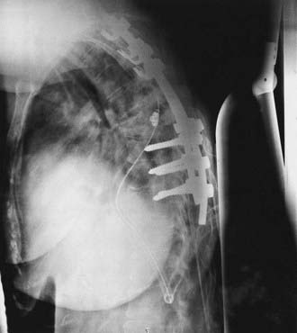
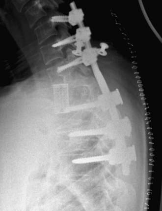
Variations in pedicle anatomy sometimes require the use of screws and hooks in combination, further increasing versatility. Hooks can serve as cephalad points of attachment of a construct that uses pedicle screws at its more caudal end (Fig. 301-2). Offset laminar hooks may also be used in conjunction with pedicle screws to augment the stiffness of the construct. Combination techniques can be especially useful at the cervicothoracic junction, where the pathology can be very challenging. Combining cervical lateral mass and possibly C7 pedicle screws with upper thoracic pedicle screws or hooks provides excellent versatility and stability at the cervicothoracic junction (Fig. 301-3).

FIGURE 301-2 Lateral radiograph showing thoracic fusion with caudal pedicle screws and cephalad laminar-pedicle hook construct.
Despite the increased level of technical difficulty associated with placement, pedicle screws provide several distinct advantages over other fixation techniques. From a biomechanical standpoint, pedicle screw–based spinal instrumentation provides the most rigid constructs and also allows versatility with corrections, including the ability to apply distraction and compression and intraoperative manipulation for correction of deformity.40–42 Pedicle screw fusion also decreases the number of adjacent segments that need to be incorporated to obtain stability compared with wire and hook systems.7 Pedicle screws can be placed at levels where there have been wide laminectomies, lamina fractures, or even partial pedicle removal. Additionally, pedicle screws do not require placement of implants in the spinal canal, as is the case with hooks and sublaminar wires.
Numerous descriptions of the appropriate starting point and angles of insertion for thoracic pedicle screws exist.3,8,43–47 Individual surgical technique often represents modifications of these descriptions based on previous training and experience, resulting in an amalgam of numerous techniques. The spectrum varies from “freehand” techniques based entirely on external anatomic landmarks, to adjuncts including fluoroscopy, use of laminotomies, and direct palpation of the pedicles, to various types of intraoperative frameless navigation systems, including systems based on imaging intraoperatively that allow tomographic verification of screw placement. Literature support exists for all these possibilities alone or in combination.44,48–50 Ultimately, the decision concerning the method for screw insertion is based on previous experience and training, accessibility to radiographic adjuncts, and comfort level of the individual surgeons.
Proper pedicle screw insertion requires the surgeon to navigate the pedicle projections in three dimensions. Because of individual variability and pathology, locating starting points and trajectory angles based only on published techniques can lead to inaccuracies. They can be used as general guidelines but must be modified by radiographic examination and intraoperative observation.3,6,8,43,45,50–54
Complications associated with thoracic pedicle screw insertion include nerve root, spinal cord, visceral, and vascular injury. An improperly placed screw in the sagittal plane may injure a nerve root. Esses and coworkers’ series of 617 cases of pedicle screw fixation contained 169 complications, 29 of which were nerve root injury.55 Matsuzaki and colleagues series of 57 cases had 6 patients with postoperative radiculopathies.56 Even in the face of spinal deformity, thoracic transpedicular fixation may be used safely. In Suk and associates’ series of 462 patients with spinal deformity, only 1 patient suffered transient neurological paraparesis from a delayed epidural hematoma.47
Several methods have been used to increase the safety of pedicle screw placement, including fluoroscopy, image guidance, direct palpation of the pedicle through laminotomies, and electrophysiologic monitoring. Electrophysiologic monitoring has been used with some success to assess the placement of lumbar pedicle screws. A screw placed completely within the pedicle requires higher voltage stimulation to achieve an electromyographic limb response than does a screw placed with a breach in the pedicle wall. However, threshold values to identify a misplaced pedicle screw in the thoracic spine are less well defined.57,58
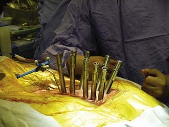
Image-guidance techniques are being used more frequently for the placement of pedicle screws to improve accuracy and safety. Newer techniques using intraoperative scan acquisition after positioning, in combination with image-guided navigation, allow reregistration if necessary and final CT scans to verify hardware placement. These techniques are especially useful in combination with minimally invasive techniques (Fig. 301-4). Although their full utility has yet to be realized, there are several potential drawbacks. These systems are not foolproof, and as with intracranial image guidance, they can provide misinformation. Also, if a surgeon’s experience involves placement only with image guidance, he or she may not recognize an aberrant trajectory. Finally, image guidance can potentially add additional time to the case.
Stay updated, free articles. Join our Telegram channel

Full access? Get Clinical Tree


