CHAPTER 296 Spinopelvic Fixation
The distinct biomechanical properties of the lumbosacral spine in conjunction with the widened cancellous pedicles unique to the sacrum make fusions of this region especially challenging.1–3 Although spine surgeons achieve rigid immobilization and fusion of the lumbosacral spine with conventional pedicle screw fixation, additional stabilization is occasionally warranted. Certain complex spine procedures, such as long segment fusions for scoliosis, place significant biomechanical stresses at the sacral fixation site.3,4 In other clinical scenarios, destructive lesions such as neoplasms or infectious processes may preclude using instruments on the sacrum altogether because of the involvement of the sacral pedicles.5 Finally, revision of symptomatic lumbosacral pseudarthrosis often requires alternate fixation points and further rigidity to achieve a bony fusion. Augmentation of a conventional lumbosacral construct with pelvic fixation should be considered under these circumstances.6
History of Spinopelvic Fixation
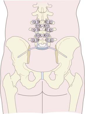
The development of spinopelvic fixation arose soon after the introduction of Harrington rods for the treatment of scoliosis.7–9 Harrington rod instrumentation was simple, consisting initially of hook-rod distraction. Two major problems became evident when attempting to fuse the lumbosacral spine with this instrumentation. First was the high rate of pseudarthrosis and second was the rate of sacral hook dislodgment.10 In response to these problems, Luque introduced the “L” rod, with the distal portion of the rod shaped to penetrate the iliac crest. Ferguson and Allen further modified the Luque system of segmental instrumentation by inserting angled rods into the iliac bones and passing them into hard cortical bone above the sciatic notch to achieve a rigid fixation of the lumbosacro-pelvic spine.11–14 This fixation method became known as the Galveston technique and increased biomechanical strength by extending use of instruments into the pelvis (Fig. 296-1).15,16 This technique became an ideal adjunct for long segment fusions in scoliosis and pelvic obliquity. However, the inherent limitations, primarily related to complex three-dimensional contouring of the rod before its insertion into the ilium, prompted the development of other techniques for lumbosacropelvic fixation. The technical challenge of contouring rods for the Luque-Galveston technique was overcome by the introduction of iliac screw instrumentation.17–19 These fully threaded iliac bolts or polyaxial iliac screws may be connected to longitudinal rod constructs either directly or with offset connectors. They have the additional advantage of modularity, facility of placement, and the capacity to place up to two screws on each side. Furthermore, the biomechanical properties of a threaded screw design, as opposed to the smooth Galveston rod, makes it less prone to pull out.
Anatomy of the Lumbosacral Spine and Pelvis
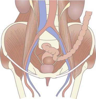
The anatomy of the lumbosacral spine and pelvis is an intricate and multifaceted osseous structure, bound by multiple ligaments and tendinous insertions externally while intertwined with viscera, vessels, and neural elements from within. The sacrum unites the two hemipelvises and serves as the base for the lumbar spine. The critical anatomy that is relevant for instrumentation of the lumbosacral region is also centered at the sacrum. The internal iliac artery and vein, middle sacral artery and vein, sympathetic chain, lumbosacral trunk, and rectum all lie directly over this structure and remain vulnerable to injury during instrumentation of this region (Fig. 296-2).2
The pelvis in its entirety is composed of the sacrum, ischium, pubic bone, and ilium. The ilium is demarcated posteriorly by the posterior superior iliac spine, which is an important landmark for iliac instrumentation (see Operative Technique section). The most rostral point of the iliac crest represents the thickest cancellous bone, which tapers incrementally in the caudal direction where there is cortical bone bordering the greater sciatic notch. The understanding of this anatomy is important to achieve solid purchase for iliac screws.20
The pelvic unit consists of two hemipelvises (connected anteriorly at the pubis) and the sacrum (connected posteriorly via the sacroiliac joints). The sacroiliac joint functions primarily to transfer axial loads to each hemipelvis and allows almost no motion.21
The bony architecture of the sacrum is distinct from that of the lumbar spine. The most rostral aspect of the sacrum has an anterior-posterior diameter of 45 to 50 mm, which tapers to 20 to 30 mm at its most caudal point.20 With the exception of the cortical bone found in the sacral promontory and alae, the sacrum has a primarily cancellous architecture with pedicles that are broader and less favorable to pedicle fixation than in the lumbar spine.3,18
Biomechanics of the Lumbosacral Spine
Transition from the mobile lumbar spine to the rigid sacropelvis results in large flexion forces at the lumbosacral pivot point. These flexion forces stress lumbosacral fixation and can lead to screw pull-out and/or pseudarthrosis.16 Augmentation of lumbosacral constructs with the addition of iliac screws may decrease the strain on sacral pedicle screws by up to 300%.
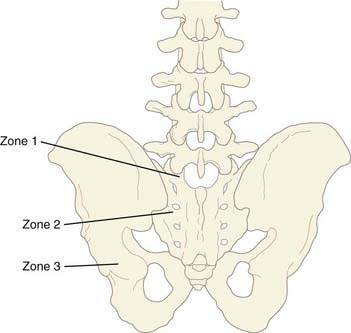
The distinct anatomic and biomechanical properties of the sacropelvic region allow for its conceptual division into three zones: zone 1 includes the proximal sacrum, zone 2 includes the alar wings to the distal sacrum, and zone 3 includes the ilium. Instrumentation of zone 1 typically involves S1 pedicle fixation. Given the broad cancellous pedicles unique to the sacrum, the trajectory of these screws should converge toward the tricortical point of the sacral promontory for optimal fixation. In zone 2, alar screws may be used to augment zone 1 instrumentation and thereby increase sacral fixation by up to 20%. Finally, the most significant biomechanical anchor for sacral fixation is provided by instrumentation of zone 3, the ilium. Iliac screws provide strong resistance to flexion and pull-out forces and are ideal to augment L5 and S1 screw fixation (Fig. 296-3).22
Operative Technique for Pelvic Screw Fixation
The patient is positioned prone on bolsters that support the chest and anterior pelvis (Table 296-1). Care is taken to position the lumbar spine in a lordotic position to minimize “flat back” syndrome. A midline incision is made above the level to be fused and extended downward to the bottom of S2. Subperiosteal dissection of the lumbar paraspinous muscles is performed with Bovie cautery and periosteal elevators. We prefer to place the hardware cephalad and do any necessary decompression of the neural elements before exposing the midsacrum and posterior superior iliac spine to limit blood loss from muscle exposure. Subsequently, subperiosteal dissection is extended over the midsacrum and laterally to expose the medial overhang of the ilium. We take care to minimize cautery around the dorsal sacral foramina to prevent bleeding and we do not cauterize into the sacroiliac joint.
TABLE 296-1 Operative Technique for Sacropelvic Fixation
4 Use a gear shift probe to create the pilot hole for the screw. |
The posterior superior iliac spine, including the distal overhang of this structure over the sacrum, is exposed. The entry point for the pelvic screw, which is 1 cm rostral to the palpated inferior overhang of the posterior superior iliac spine and 1 cm below the superficial ridge of the posterior superior iliac spine, is identified (Fig. 296-4, A). It is important to place the screw head deep to the superficial ridge of the posterior superior iliac spine because this structure is the most prominent bony structure that individuals feel when they sit against a hard backed chair (Fig. 296-4, B).
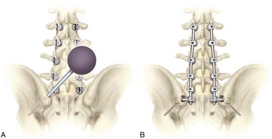
Following the exposure, the pelvic screw entry point is decorticated with a small drill. The pelvic gear shift is then placed into the entry point and aimed toward the thick bone, which is just superior to the greater sciatic notch and potentially onward toward the anterior inferior iliac spine, taking care not to violate the top of the acetabulum. This optimizes the bone to screw interface. The gearshift is gradually advanced 60 mm or more to reach the target bone above the greater sciatic notch. Care must be taken not to enter the greater sciatic notch itself to avoid injuring the neurovascular structures that traverse it (i.e., the superior gluteal vessels and sciatic nerve). Anteroposterior fluoroscopy typically provides adequate guidance to direct the pelvic gear shift to the bone just superior to the greater sciatic notch. The angle of the gear shift from the entry point is typically 30 to 45 degrees inferiorly in the coronal plane and 30 to 45 degrees anteriorly in the axial plane (see Fig. 296-4, A).
Subsequently, the pelvic screw is then threaded into the pilot hole until the head of the screw is recessed into the posterior superior iliac spine. This step in screw placement is important because recession of the screw head into the bone prevents the patient from feeling a prominent screw head when he or she sits against a hard-backed chair. It is important to note that some prominence of the pelvic screw heads may be unavoidable in thin patients who have limited muscular covering of the lumbosacropelvic area. However, burying the screw heads below the superficial portion of the posterior superior iliac spine helps to prevent superficial skin breakdown and pressure sores in these patients.23


Stay updated, free articles. Join our Telegram channel

Full access? Get Clinical Tree


