Fig. 8.1
Schematic diagram of the basal ganglia–thalamocortical circuitry under normal conditions (a) and in Parkinson’s disease (b). In Parkinson’s disease, decreased excitatory inputs from the substantia nigra compacta (SNc) to striatal D1 neurons lead to the disinhibition of globus pallidus internus (GPi) neurons and increase the inhibitory output to the thalamus (direct pathway). Decreased inhibitory projection from the SNc leads to the disinhibition of striatal D2 neurons, and inhibition of globus pallidus externus (GPe) neurons. Decreased GPe activity induces overactivation of the subthalamic nucleus (STN) and consequently of the GPi (indirect pathway). Black arrows inhibitory projections, white arrows excitatory projections
The optimal stimulatory site for GPi-DBS in the treatment of PD is the sensorimotor region located in the posterior ventrolateral region of the GPi. The association system loop projects dorsally to the GPi. Moreover, the rostromedial part of the GPi contains projections from the limbic system. The sensorimotor region of the GPi is somatotopically organized, with the face and upper and lower limbs arranged in order from the ventral to dorsal side.
As previously stated, the GPi is a larger nucleus compared to the STN. However, accurate targeting in the sensorimotor region reduces the transport of stimulatory effects to the limbic system, and reduces the risk of neuropsychological side effects.
8.4 Surgical Methods
8.4.1 Patient Selection
Patient selection is a critical step for obtaining optimal benefits and decreasing morbidity. Several factors should be considered when determining if a patient is a suitable candidate for GPi-DBS. The most important point is to confirm that a patient has been diagnosed with idiopathic PD prior to surgery (Bronte-Stewart 2003). Patients with other Parkinson syndromes, such as progressive supranuclear palsy (PSP) and multiple system atrophy (MSA), will not benefit from DBS surgery. Therefore, a patient’s response to levodopa is the best indicator of suitability for GPi-DBS. Severe drug-induced dyskinesia and motor fluctuations, such as wearing-off and on-off phenomena, impair the abilities of daily living despite appropriate medication therapy. The long-term problems associated with levodopa therapy may occur anywhere from 3 to 10 years after treatment initiation, but GPi-DBS can improve these symptoms. Tremor is also fairly suppressed by GPi-DBS as well as thalamic (Vim) stimulation. Nevertheless, it is not advisable to use either STN-DBS or GPi-DBS in elderly patients with brain atrophy and those with dementia.
8.4.2 Preoperative Preparation
Preoperative assessment is essential for evaluating a patient’s suitability for surgery and their risk of poor postoperative outcome and complications. Videotaped recordings of the patient’s behaviors are useful for comparing pre- and postoperative statuses. The Unified Parkinson’s Disease Rating Score (UPDRS) is a widely used rating scale for following the course and symptoms of PD, and patients should be assessed both on and off medication. Neuropsychological testing is also necessary to evaluate patients for dementia and cognitive disturbance.
The night prior to surgery, antiparkinsonian medications are usually stopped to permit the pronouncement of PD symptoms during surgery. Any anticoagulant and platelet aggregation medications should be discontinued at least 7–10 days preoperatively to avoid intracerebral hemorrhage, which is the most serious complication associated with stereotactic surgery.
8.4.3 Stereotactic Frame Application
Stereotactic surgery is performed under local anesthesia; a mixture of lidocaine, marcaine, and epinephrine are injected into the frame pin site. An appropriate dose of propofol can be given prior to pin insertion to minimize suffering when placing the frame. During surgery, care should be taken to maintain blood pressure within a normal range to avoid intracerebral hemorrhage.
A variety of stereotactic head frames are available, such as Leksell, CRW, and Riechert–Mundinger. Surgical procedure details differ between institutes, and stereotactic surgeons should master the use of their institution’s apparatus. During frame placement, it is important to place the frame with its axes orthogonal to the standard anatomical planes of the brain (Machado et al. 2006; Starr 2002) (Fig. 8.2). Earplugs may be used to facilitate straight frame placement while applying the pins. Moreover, the base of the frame should be applied parallel to a line between the inferior orbital rim and the external auditory canal, which is approximately parallel to the anterior commissure–posterior commissure (AC–PC) line. When indirect targeting is used, it is important to lay axial targeting image planes coplanar to the AC–PC plane, as the placement will be less accurate if deviations are present between both planes.
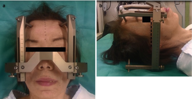

Fig. 8.2
Application of the stereotactic head frame (Leksell). (Left) The head is centered in the frame, so that the midline on the head is aligned to the center of the frame. Note the midline of the head is parallel to the posts of the frame. (Right) The lateral view shows the base of the frame is placed parallel to a line between the inferior orbital rim and the external auditory canal
Once the frame is in place, preoperative imaging, such as computed tomography (CT), magnetic resonance imaging (MRI), and ventriculography, is performed to construct the stereotactic images required for DBS surgery. Several image-guided software systems are available to integrate data sets from multiple imaging methods. We use a StealthStation Framelink package (Medtronic navigation, Louisville, CO) to generate integrated images by fusing MR images obtained preoperatively without the frame, with CT images obtained immediately after frame placement (Fig. 8.3). The CT images are always used as the main reference during surgery.
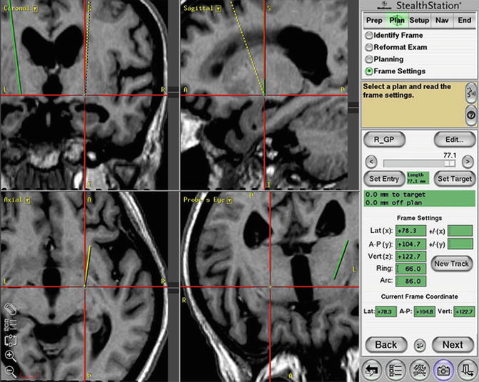

Fig. 8.3
Determining the target and planning the trajectory by using the T1-magnetization-prepared rapid gradient-echo (MPRage) sequence on the software StealthStation Framelink. The trajectory avoids the lateral ventricle while targeting the globus pallidus internus (GPi)
8.4.4 Operative Procedures
The most important step of GPi-DBS surgery is accurate electrode placement into the optimal portion of the GPi. To do this, it is important to perform each of the three steps in the operative procedure appropriately, including target setting, microelectrode recordings (MERs), and macrostimulations.
8.4.5 Target Setting
There are two methods for defining the initial anatomical target in GPi: direct and indirect targeting. Indirect targeting is based on a standardized stereotactic atlas established on AC and PC landmarks. Direct targeting is based on the imaging data set of an individual’s own anatomy (Lemaire et al. 1999). Direct targeting seems to have obvious benefits over the indirect method; however, both of these techniques have disadvantages. We employ a hybrid of these two methods to define the initial target.
Indirect targeting has been the traditional method employed in stereotactic neurosurgery. It is based on a standardized stereotactic atlas, and uses fixed distances from the midcommissural point (Pallavaram et al. 2008). The typical GPi coordinates are 19–21 mm lateral to the midline, 2–3 mm anterior to the midcommissural point, and 4–5 mm ventral to the intercommissural plane. It is easy to identify the commissures on MRI, and target coordinates are readily available in the literature. However, a disadvantage of indirect targeting is the existence of discrete variations in the anatomy of the brain between different individuals. Care should be taken to account for sufficient individual variation in the lateral coordinate by expanding the range to 16–23 mm from the midline.
Direct targeting is based on MRI visualization of the structures, and it is helpful for making fine adjustments to the indirect coordinates in an attempt to compensate for individual variation in nuclear location. As the GPi, adjacent OT, and internal capsule can be visualized via inversion recovery and T2 images, the lateral and vertical coordinates are then checked with respect to the individual’s nuclear anatomy. The target should be placed in the posterior third of the ventral GPi directly over the OT, which passes just ventral to the motor territory of the GPi, and can be used as a targeting landmark. When the borders of the GPi are not perfectly visualized, the vertical and lateral coordinates can be checked to ensure that they correspond to the dorsal border of the OT on a coronal T1-MR image in 3D mode, just traversing the mamillary bodies (Fig. 8.4).
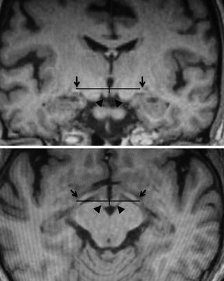

Fig. 8.4
Stereotactic targeting of the globus pallidus internus (GPi) on the reformatted T1-magnetization-prepared rapid gradient-echo (MPRage) images. (Upper) Coronal image at 3 mm anterior to the midcommissural point, which usually traverses the mamillary bodies. (Lower) Axial image passing through the dorsal border of the optic tracts (OTs). The horizontal and vertical coordinates are determined from the dorsal border of the OT. Arrowheads mamillary body, arrows optic tracts
8.4.6 Patient Position and Opening
The head frame is secured to the operating table by using the Mayfield with an adaptor. The patient is positioned supine on the operating table, with the knees flexed and the head of the table elevated to about 30°. This position avoids cerebrospinal fluid (CSF) leakage and prevents excessive intraoperative brain shift (Fig. 8.5).
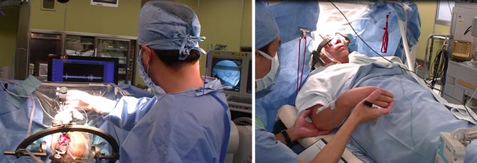

Fig. 8.5
Operative setup and patient positioning. (Left) The sterile area is located at the top of the patient’s head. The C-arm is draped. The monitors displaying the microelectrode recordings and fluoroscopic image are placed over the operating table, such that the surgeon can easily view the monitors during the procedures. (Right) The patient is positioned supine with the head of the table elevated. The sterile transparent drape acts as a barrier between the sterile head area and the nonsterile area where the examiner stands, while providing good visualization of the patient’s face during the surgery
The entry point and final trajectory are established using T1-MRI in 3D mode with the aid of planning software to avoid the ventricles, sulci, and vessels along the electrode trajectory. We usually place the burr hole 1–2 cm anterior to the coronal suture and 2.5–3 cm from the midline. The planned burr hole sites are anesthetized, and the scalp is incised in a semicircular fashion (Fig. 8.6).
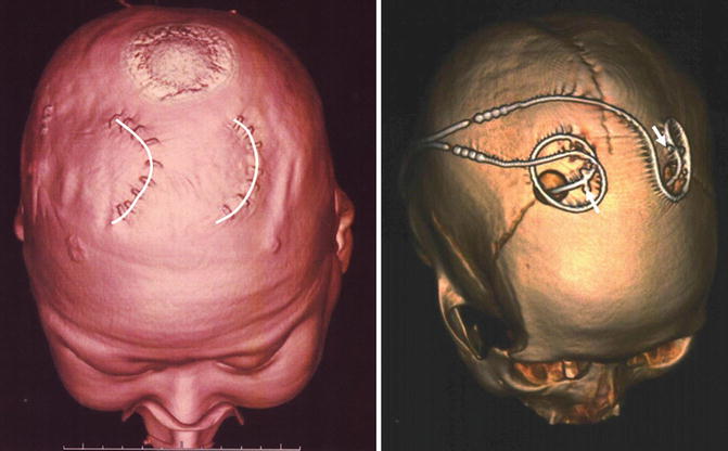

Fig. 8.6
Postoperative 3D-computed tomography (CT) images showing the location of the skin incisions (left, semicircular lines) and burr holes (right). The deep brain stimulation (DBS) leads were fixed using titanium miniplates (right, arrows)
8.4.7 MERs
Several factors may prevent targeting accuracy when only preoperative image sets are used; therefore, image-guided anatomical targeting alone is not sufficient for optimally placing a DBS lead (Guridi et al. 2000; Starr 2002).
The accuracy of targeting is limited by the mechanical properties of the stereotactic system itself. Moreover, anatomic targeting precision can be decreased by MRI slice thickness and distortion effects, brain shift due to CSF leakage during surgery, and imperfect visualization of the GPi. Hence, physiological studies are important for confirming or adjusting final placement.
Using MER, the structures surrounding the GPi that will be traversed by the electrode can be identified on the basis of their characteristic firing patterns. Furthermore, efficacy and side effects are assessed by macrostimulation. As the electrode passes in close proximity to neurons, the unit activity from the neurons is transmitted through the microelectrode and displayed on a computer monitor.
Usually, single-unit extracellular action potentials are recorded using high-impedance (0.1–1.0 MΩ at 1,000 Hz) tungsten or platinum-iridium microelectrodes, with a 15- to 25-μm tip diameter. The impedance of larger electrode tips is too low to make single-unit discriminations from neuronal activity recorded near the tip. The impedance of smaller-sized electrode tips is higher; thus, only single cells with lower background recordings are achieved. The MERs are started from 20 mm above to 4 mm below the potential target, depending on individual anatomical findings. The neuronal activity in each brain structure has a characteristic pattern (Fig. 8.7). The major structures identified by MER are the striatum, GPe and GPi, internal and external medullary laminae, nucleus basalis, OT, and internal capsule (Vitek et al. 1998).
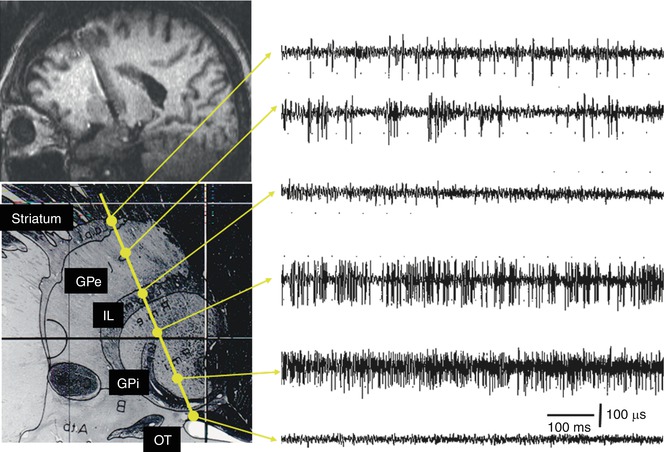

Fig. 8.7
Chart showing the characteristic neuronal activity of a typical track targeting the globus pallidus internus (GPi). The microelectrode passes through the striatum, globus pallidus externus (GPe), and internal laminae (IL), and finally enters the GPi, where a high-frequency tonic neuronal activity is recorded. Note the ventral position of the optic tract (OT)
8.4.7.1 Striatum
The microelectrode typically first encounters striatal cells, and then GPe cells prior to reaching the GPi. The striatum is separated from the GPe by the external laminae. Striatal neurons mainly have low spontaneous discharge rates (lower than 10 Hz) with a tonic pattern and have a relatively long duration with high-amplitude action potentials.
8.4.7.2 GPe
In the GPe, two distinct patterns of spontaneous activity are recorded. Most GPe neurons fire in a regular fashion with high-frequency discharges of 30–60 Hz separated irregularly by brief pauses. Approximately 10–20 % of GPe neurons fire at a low frequency (around 10 Hz) with high-frequency, short-duration bursts.
8.4.7.3 GPi
The GPi is separated from the GPe by an approximately 1-mm-thick internal laminae of white matter that can be identified by the lack of cellular activity and the frequent presence of border cells. After passing the internal laminae, the entrance to the GPi is easily recognized by a sharp, distinct increase in activity. In the GPi, neurons generally have a tonic discharge pattern with a high frequency (higher than 70 Hz in PD), but without the distinct pauses observed in the GPe. In addition, some neurons fire synchronously with the patient’s tremor (tremor-related cells).
The location of the sensorimotor region of the GPi is found predominantly in the structures’ posterolateral portions. A substantial number of neurons in the motor region modulate their firing rate in response to passive manipulations and active movement of the extremities and orofacial structures on the contralateral side of the body. The anteromedial region of the GPi is related to nonmotor associative functions; this finding is consistent with those of animal experiments. There is a general somatotopic organization in the motor region of the GPi. Cells representing the leg tend to be more dorsal and medial to those representing the arm and face. The base of the GPi can be identified by an abrupt diminution in neuronal activity as the microelectrode exits the GPi, at which point border cells may be encountered.
Approximately 1–2 mm below the inferior margin of the GPi is the OT. There is usually no spontaneous activity within the OT, and although monophasic spikes are sometimes recorded, they can be identified as OT by light-evoked fiber activity. Microstimulation evokes visual sensations at currents less than 20 μA.
During typical penetration through the longer central extent of the GPi, the neuronal activity in a 6-mm-long segment of the GPi is recorded, and the OT is identified 2 mm below the GPi base. If the region of GPi neuronal activity is shorter than 6 mm and the OT cannot be identified, it is possible that the track was not optimal, and a second track should be considered.
Subsequent tracks should be at least 2 mm away from the first track. The second track is made either anterior or posterior to the initial track to confirm the posterior border, depending on the apparent location of the first track within the GPi. Additional tracks are made either laterally or medially to delineate the lateral border of the GPi.
8.4.8 Macrostimulation
Prior to internalizing the lead, we perform a final location check by testing it intraoperatively with macrostimulation, which can elicit visual, motor, or cutaneous sensory responses by affecting structures near the probe. Rigidity; finger tap; opening and closing of hand; heeltap; and observations of tremor, voice, and vision are recorded during test stimulation. Owing to the proximity of the internal capsule and OT, it is important to determine the threshold of stimulation-induced phenomena. The corticobulbar tract (CBT) and corticospinal tract (CST) in the internal capsule are identified by evoking muscle contractions. If dysarthria, conjugate eye movement, or tonic facial contraction is elicited at low stimulation thresholds, the lead is too close to the CBT and should be moved posterolaterally. If muscle contractions of the contralateral hand and leg are evoked at low stimulation thresholds, the lead is too close to the CST and should be moved anterolaterally. If CBT- or CST-related responses are not observed at high intensity stimulation, it indicates electrode failure or poor positioning (too anterior, lateral, or superior) (Fig. 8.8).
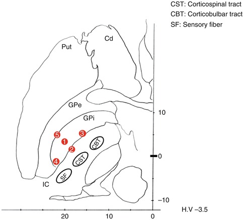

Fig. 8.8
Macrostimulation-induced phenomena and possible electrode locations. ① Optimum location: usually, tremor and dyskinesia disappear. Rigidity also diminishes. ② Medial shift: muscle contractions of the contralateral hand and leg are evoked at a low stimulation threshold because of the activation of the corticospinal tract (CST). ③ Anteromedial shift: dysarthria, conjugate eye movement, or tonic facial contraction is elicited because of the activation of the corticobulbar tract (CBT). ④ Posterior shift: numbness is evoked on the contralateral face and hand because of the activation of the sensory fiber (SF). ⑤ Lateral shift: no evoked responses are shown during a high-intensity stimulation
As the typical thresholds of CBT/CST responses evoked by Lead Point electrodes (Medtronic, Louisville, CO) are within a range of 3–5 mA, a trajectory with a threshold of <2.5 or >5 mA is not optimal. Because the OT passes beneath the motor region of the GPi, if an optimal track inferior to the GPi is stimulated, most patients report transient visual flashes. Although intraoperative test stimulation is not used for assessing therapeutic benefits, if a tremor is present, it is immediately reduced during test stimulation. Other symptoms besides tremor do not respond intraoperatively.
Motor symptoms in PD may be either partially or completely suppressed by mechanical insertion of the electrode itself without electrical stimulation. Observation of this so-called microlesion effect is evidence that the electrode is positioned appropriately within the motor region of the GPi, even though failure to observe a microlesion effect does not necessarily predict a poor chronic stimulation outcome.
Stay updated, free articles. Join our Telegram channel

Full access? Get Clinical Tree


