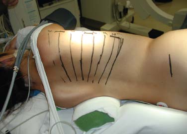
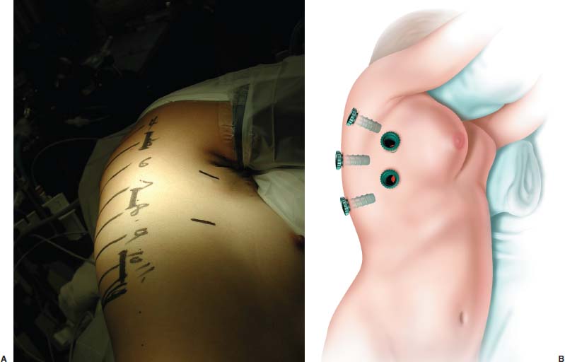
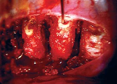
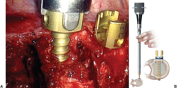
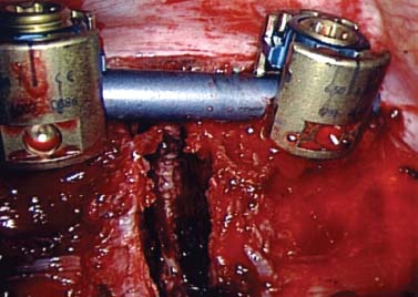
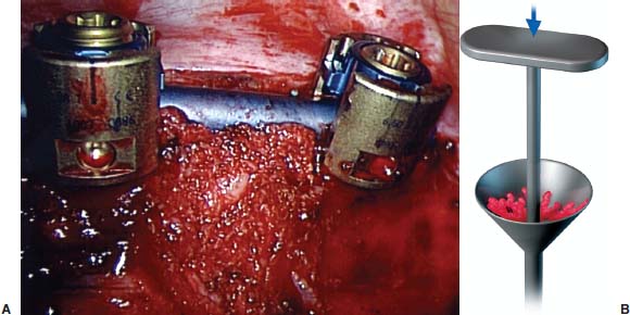
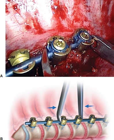
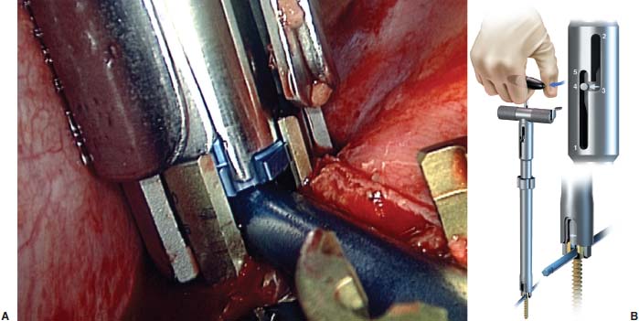
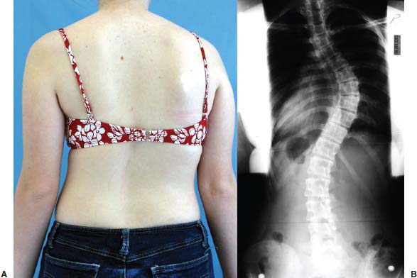
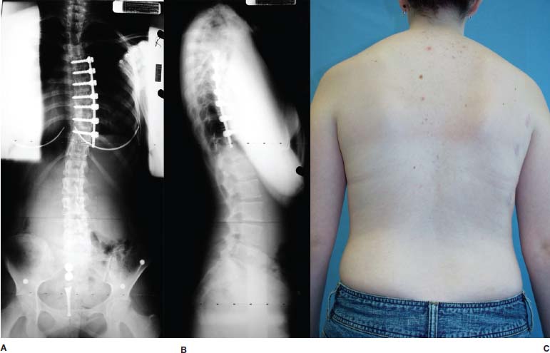
Thoracoscopic anterior scoliosis correction incorporates minimally invasive techniques with anterior thoracic instrumentation strategies for the correction and fusion of scoliosis. This approach, which is largely used for adolescent idiopathic scoliosis (AIS), avoids much of the morbidity associated with the traditional open anterior or posterior approaches. Anterior thoracic scoliosis correction is based on theories that AIS is generally associated with a hypokyphotic thoracic spine—relative anterior overgrowth, which leads to the rotational deformity and lateral deviation we see as scoliosis.1 Anterior column overgrowth is thus treated with an anterior column shortening procedure. This is accomplished by disk excision and compressive anterior instrumentation of all the vertebrae of the measured curve. This has proven to be successful with the open approach2 and is now possible (in select cases) via minimally invasive thoracoscopic methods. The thoracoscopic approach, however, requires special attention to detail and is thought by some to be too demanding and/or tedious for widespread implementation. There is no doubt that the learning curve for this procedure is substantial,3 but deliberate training and cautious adoption can result in excellent outcomes with reduced patient morbidity. The details of this chapter are meant to supplement such a training experience (not replace it), and it is hoped that the “tricks” as well as the “pitfalls” can be shared for the benefit of our patients. Although this represents current thoughts and techniques, surgery is always in evolution, one hopes in the direction that leads to true progress. Expect what we do today to be different tomorrow. Indications The procedure described in this chapter is primarily designed for idiopathic thoracic scoliosis with curves greater than 40 to 50 degrees (depending on maturity and truncal deformity), but less than 70 to 80 degrees. The curve pattern should be amenable to selective thoracic instrumentation between T4 and L1. This includes many Lenke I and King II or III curves. The size of the patient and sagittal profile are also important. The ideal size of the patient remains to be identified clearly, but it likely falls between 40 and 60 kg. Patients smaller than 40 kg provide additional challenges for secure vertebral body fixation, particularly at the proximal extent of the construct, where the size of the thoracic vertebrae may not be sufficient to hold a vertebral body screw. Patients who are too large may overstress a single rod construct to the point of fatigue failure before a solid arthrodesis occurs. Contraindications Excessive kyphosis is also problematic for these constructs. Anterior surgery is by its nature kyphogenic, and patients who begin with greater than 30 to 40 degrees of sagittal curvature (between T5 and T12) should be avoided to prevent excessive postoperative kyphosis. Rod failure should be expected if kyphosis correction is attempted with a single anterior rod system without substantial anterior column interbody support (which may be difficult to achieve in the upper thoracic spine due to soft end plates). Other contraindications include those of thoracoscopic surgery in general. These include conditions that result in such intrathoracic pleural adhesions as prior ipsilateral thoracic surgery or infection. The patient must be able to tolerate single-lung ventilation. Collapse of the ipsilateral lung is critical to the safe visualization of the spine. Large curves greater than 80 degrees and those with substantial rigidity may be better dealt with by posterior or combined approaches. Surgical Equipment Thoracoscopic surgery is very much equipment dependent, the quality of which can have a significant impact on outcome. This requires high-quality endoscopes and three-chip camera video systems. A 10 mm diameter endoscope with angled viewing (0 to 45 degrees) is essential to visualize all of the aspects of the spine and implants. The equipment required can be broken down based on the various stages of the procedure: exposure, disk excision, instrumentation, and bone grafting. Endoscopic exposure of the spine begins with singlelung ventilation. This can be accomplished by one of several methods, the most common of which uses a double-lumen endotracheal tube. After the ipsilateral lung is collapsed, thoracoscopic portals between the ribs allow access to the spine. The specialized equipment required to expose the spine includes an endoscopic retractor for the lung, peanut dissectors, a suction/irrigation device, and a harmonic scalpel. The harmonic scalpel is an ultrasonic device that can be used for cutting the pleura, coagulating the segmental vessels, and incising the anulus of the disk. By contrast, disk excision is largely dependent on mechanical tools typical to spine surgery, and including rongeurs, curettes, and mechanical end-plate shavers that have been modified in length and dimension to pass through 11.5 mm thoracoports. The tools required for placement of implants thoracoscopically are available in the Frontier anterior scoliosis set (DePuy-Acromed, Inc., Raynham, MA). Image intensification with a C-arm is required to determine the intraoperative spinal level and is also important in assessing screw trajectory. Additional specific tools are utilized for iliac crest bone graft harvest typical to harvesting posterior iliac crest; however, this bone graft, after harvesting, is placed through a bone mill that morselizes the graft, allowing it to be delivered through a plunger system. Operating Room Setup The patient is positioned on a radiolucent table in the lateral position with an axillary roll. The surgeon and assistant may stand on either side of the patient, although we find it easier for surgeons to orient their mind’s eye when the surgeon and assistant stand on the anterior side of the patient, with the endoscopic tower placed facing them on the posterior side of the patient. The harmonic scalpel generator, electrocautery generator, suction/irrigation, and cell saver are positioned at the head of the operating table on either side of the anesthesiologist. Steps of the Surgical Procedure One the critical initial steps of the procedure involves marking the patient to plan for the location of the thoracoscopic portals to allow proper screw orientation within each vertebra to be instrumented. With the patient in the direct lateral position, the image intensifier is used to mark a longitudinal line on the side of the patient that corresponds to the sagittal alignment of the spine. The midlateral position of the vertebra to be instrumented is marked on the lateral chest wall, and this typically approximates the posterior axillary line. With the image intensifier brought underneath the table for an anterorposterior projection, the orientation of each vertebra to be instrumented in the frontal plane is also marked on the posterior aspect of the patient (Fig. 15–1). The intersection of a line marking the frontal plane orientation of a vertebra and that line marking the midlateral portion of that vertebral body locates the ideal chest wall entry site to obtain an appropriate screw trajectory. Six to eight screws may be required in a typical scoliosis construct. This will therefore require a corresponding number of trajectories through the chest wall. Rather than making a skin incision for each screw trajectory, however, two or three screws can typically be placed through a single skin incision by stretching the skin incision proximally and distally, above and below, the corresponding ribs. Using this strategy, typically three and occasionally four portals are required on the posterior axillary line, with two additional portals placed along the anterior axillary line (Fig. 15–2). The anterior portals are used for visualization of the spine as well as much of the dissection, diskectomy, and bone grafting work. The chest and iliac crest are widely prepped and draped, and the initial aspect of the surgery involves harvesting the posterior iliac crest bone. This graft is placed through a bone mill to create a soft, morcellized autogenous bone graft material. FIGURE 15–1 Posterior skin markings of the angulation of each vertebra to be instrumented. FIGURE 15–2 The planned anterior and posterior portals are marked on the chest. (A) Intraoperative photograph and (B) artist’s depiction. The thoracoscopic approach to the spine is initiated with the two anterior axillary line portals. The 11.5 mm diameter rigid thoracoports are placed through 1.5 cm long incisions. Lung deflation is confirmed with direct visualization through the port. The third port to be placed is the inferior most posterior portal that will be used for both disk excision and screw insertion. If required or desired, the most inferior portal can be extended to create a small thoracotomy that will allow direct visualization through the wound. Some of the most challenging levels to be addressed thoracoscopically are those of the lower thoracic and thoracolumbar junction, and a small thoracotomy may substantially facilitate the treatment of these lower levels. With these three portals established, a fan retractor is placed for lung retraction. This is frequently required during the initial stages of the operation because the atelectasis of the lung is not yet complete. The levels to be instrumented are determined by counting from the most proximal rib head, realizing that the first rib may be difficult to visualize and is most easily located by direct palpation with such an instrument as a peanut dissector. Radiographic confirmation with a K-wire is also required. The spine is exposed by longitudinal incision of the pleura ~5 mm anterior to the rib heads. The segmental vessels are coagulated and divided using the harmonic scalpel. If exposure to L1 is required, the insertion of the diaphragm over the T12–L1 disk will require incision as well. Circumferential exposure of the spine is achieved by stripping the pleura and segmental vessels off the anterior aspect of the spine, using a combination of blunt dissection and the harmonic scalpel. Gauze sponges packed in this interval between the aorta/esophagus and the spine substantially improve this exposure and allow the disk to be widely excised, particularly on the convex side, safely. Disk excision is initiated with incision of the anulus and anterior longitudinal ligament using the harmonic scalpel. An upbiting rongeur is used to begin the diskectomy on the anterior and concave aspects of the disk space. The diskectomy then proceeds to the convex rib head. It is important to limit vertebral body bone bleeding, which impairs visualization into the depths of the disk. A nearly bloodless disk excision is possible in many AIS patients if the end plate cartilage is peeled off the vertebral body without biting into the bone of the vertebral body itself. An end plate reamer may be used once the disk is completely excised to confirm flexibility. Hemostasis is achieved following disk excision by packing the disk space with Surgicel. Disk excision proceeds in a proximal to distal fashion and requires adjustment of the portals and instruments placed through these portals to maintain ideal visualization into the depths of the disk space. The 45-degree angled endoscope is placed one portal proximal or distal to the portal used for disk excision, with the portal for disk excision being placed exactly in line with the disk. To achieve ideal access, it is frequently required to move the portal above or below a rib (using the same skin incision to do so). With disk excision completed, reconstruction of the sagittal plane is performed, with structural allograft placed at levels inferior to T11. This structural grafting is typically in the form of a fibular ring cut to an appropriate height based on the preoperative sagittal alignment of the lower thoracic spine and thoracolumbar junction. The graft is placed directly through the posteroinferior skin incision, with the rigid port removed. Prior to final placement of the allograft, cancellous autografting is performed in the concave side of the disk space, with the allograft placed in the anterior aspect of the disk space. A true endoscopic disk space distractor is not used; however, direct pressure from an assistant to the posterior aspect of the spine is often sufficient to accomplish opening of the disk space for excision and grafting purposes. Instrumentation Insertion of the vertebral body screws requires two additional posterior axillary line portals (three total). The position has been planned previously with the image intensifier; however, before making a skin incision, it is confirmed by placing a K-wire through the chest wall at each proposed portal site. The image intensifier anteroposterior view is used to be sure the orientation of the K-wires is in line with the vertebra (parallel to the end plates) (Fig. 15–3). A longitudinal 2 cm skin incision is made, and with blunt dissection just anterior to the scapula through the musculature, the chest cavity is entered with Mayo scissors. A 15 mm rigid thoracoport is placed, and direct visualization down the port should line up with the lateral aspect of the superior vertebral body. Direct visualization is important to gain a threedimensional orientation for the screw trajectory. The starting point for screw insertion is in the midvertebral body just anterior to the rib head. An awl and tap are used to establish the screw path. Screw length is determined by probing the tapped screw path and judging length from the calibrations on the probe. The screw should engage the far cortex, but it should not be excessively long. Screws are available in 2.5 mm increments to accommodate the variety of thoracic vertebral dimensions. FIGURE 15–3 Appearance of the spine after diskectomy. The K-wire was placed through the chest at the planned site for the proximal posterior portal. The alignment of the K-wire was confirmed with the image intensifier before making the skin incision for this portal. The K-wire is in the T6 vertebra at the site for screw placement. Subsequent screws are placed in similar fashion, moving the thoracoport distally one rib interspace at a time. Two or three screws can be placed through each skin incision. The alignment of each screw relative to the last is critical to the success of subsequent rod insertion (Fig. 15–4). Visualizing directly through the portals (both posterior and anterior) as well as with the endoscope and image intensifier ensures proper screw placement. The value of looking directly down the portal to judge screw placement cannot be overemphasized. After confirming screw position with the image intensifier, adjustment of the depths of the screws may be required. An incompletely inserted screw will make rod connection difficult in adjacent screws. Rod length is determined based on direct measurement with a malleable calibrated template inserted through the distal portal. Shortening of the spine by 1 to 1.5 cm should be anticipated due to compression. The rod is contoured to the desired degree of kyphosis and scoliosis based on the anticipated and desired postoperative alignment. FIGURE 15–4 The screws are inserted to achieve bicortical purchase. (A) Intraoperative photograph and (B) artist’s depiction. Just as screw insertion is initiated proximally, so is engagement of the rod, beginning with the most tenuous proximal screws. The hex-end rod holder maintains the orientation of the contoured rod (placed through the distal skin incision without a portal) as the proximal screws are engaged. A locking cap captures the rod and is tightened to fix the rod position (length and rotation). Subsequent screws are captured by cantilevering the rod into position (Fig. 15–5). As each screw cap is inserted, that level is bone grafted with the graft delivery tube. Morcellized autogenous graft (harvested from the posterior ilium or ribs) should fill the disk space prior to compression between the screws (Fig. 15–6). Compression is achieved with the endoscopic compressor placed directly through an anterior (proximal levels) or posterior (distal levels) skin incision. Compression of the proximal levels needs to be applied gently and with caution to prevent the screws from loosening in the bone (Fig. 15–7). More aggressive compression is applied to the apical levels if bone quality allows. Rod translation to the screws is greatly facilitated by the combination approximator/ cap inserter tool. Through the distal incision the device is attached to one of the distal screws (usually the second one from the bottom) and used to push the rod into the more proximal screws sequentially (Fig. 15–8). The proximal caps are inserted with the grafting, compression, and the cap locking routine repeated at each level. The approximator may be required at the most distal level as well, with compression at this level applied across the structural graft (as well as additional morcellized autograft that was placed following diskectomy). Use of this structural graft prevents distal kyphosis as well as overcorrection in the coronal plane. FIGURE 15–5 The rod has been locked to the proximal screw, with the cap engaged in the second screw (but with the set screw loose). This is the appearance just prior to bone grafting and compression. Pleural closure completes the procedure and is accomplished with an endoscopic stitching device. A running closure covers the implants and maintains the bone graft in position postoperatively. A chest tube is required for several days postoperatively and is placed once the chest has been irrigated and loose debris removed. Lung reinflation is confirmed, and bronchial suctioning of the dependent lung is performed to reduce the incidence of postoperative atelectasis due to mucous plugs. Once the chest tube has been removed, a postoperative thoracolumbosacral orthosis (TLSO) is prescribed for 3 months that is to be worn when the patient is out of bed. FIGURE 15–6 Autogenous iliac crest graft has been delivered to fill the disk space. (A) Intraoperative photograph and (B) artist’s depiction. FIGURE 15–7 Segmental compression is applied with the endoscopic compressor. (A) Intraoperative photograph and (B) artist’s depiction. Complications and Avoidance There are several times during this procedure that complications may develop and compromise the outcome. Minimizing and managing these challenges is key to the success of the procedure. The back-up plans include converting to an open approach and using posterior implants. Many complications of a thoracoscopic procedure can be avoided if ideal visualization is maintained. This requires proper equipment (high-quality, angled optics), proper endoscope placement and camera orientation, limited bleeding, and appropriate retraction (lung, diaphragm, and great vessels). Bleeding during bony spinal surgery is unavoidable; however, it can be minimized, and doing so allows safe disk excision, particularly of the far-side anulus. Minimizing blood loss begins with deliberate use of the harmonic scalpel during exposure of the spine, coagulating all the small vessels along the spine as the circumferential stripping is performed. Bone bleeding can be addressed with wax applied with an Endo-peanut. Bleeding from the exposed bony end plate of the vertebral body is expected, but it can be substantially reduced if the technique of disk excision avoids early penetration of the cancellous bone. Caudal exposure to T12 and L1 requires diaphragm retraction, which can be a challenge endoscopically. This is achieved with an angled fan retractor placed from the anterior proximal portal, pushing the diaphragm distally. To expose the L1 body, the diaphragm must be split for ~2 cm at its insertion. One option to facilitate this aspect of exposure is to perform a limited thoracotomy at the site of the inferior portal. A 5 to 7 cm incision allows standard retractors and rongeurs to be utilized at these more difficult distal levels. FIGURE 15–8 The cap inserter/approximator tool allows the rod to be cantilevered into the distal screws while applying the cap. (A) Intraoperative photograph and (B) artist’s depiction. Engaging the rod into the screws can be problematic when the screws are malpositioned. The screws should be placed in the midvertebral body and directly lateral. Employ every means possible to ensure absolutely this position for each screw. The most useful approach we use is looking directly through the rigid thoracoport. The orientation of the vertebral body can be seen with the Surgicel removed from the adjacent disk spaces, as can the position of the proximal screw that needs to be matched. The image intensifier can be used for confirmation, but nothing replaces the direct bird’s-eye view through the port. A few extra minutes getting the screw position perfect will save hours of frustration at the time of rod insertion. Proper screw alignment does not guarantee simple engagement of every locking cap, although most of these issues are straightforward to deal with. If a cap will not turn and capture the screw head, stop and check the following. First, be sure that the set screw is not advanced through the end of the cap, preventing full cap insertion. If so, back out the set screw and reattempt. Second, be sure the rod is fully reduced into the screw head. This can be a problem if the screws are inserted to different depths—check and adjust based on the image intensifier view before rod insertion. Use the rod approximator to seat the rod fully. If the cap will not turn, resist the temptation of forcing the cap to engage the screw head. If it takes more than two fingers to click in the cap, stop and check all of the preceding items. Many of the complications of open anterior thoracic instrumentation remain with the endoscopic approach and include implant-related problems (e.g., loss of proximal fixation and pseudarthrosis). Proximal fixation requires bicortical purchase with a cancellous designed screw. The diameter should be as large as possible without risking vertebral body fracture (5.5 or 6.5 mm diameter). In addition, a scoliosis bend in the upper section of the rod limits the force application to the proximal screws during rod cantilevering. This can also be accomplished by using a washer or staple under the proximal screw. It is also important to limit the compression applied at the proximal level because screw plow through the near cortex reduces the resistance to later axial screw pullout. Pseudarthrosis prevention requires attention to detail during disk excision and grafting, as well as avoidance of high-risk patients. Single-rod constructs have a limited fatigue life that mandates early solid fusion. As such, the disk spaces must be filled with high-quality autogenous bone. A postoperative TLSO also seems prudent. Patient selection can limit this complication by avoiding large patients (i.e., less than 60–70 kg), smokers, and those with kyphosis (i.e., T5–T12 less than 30–40 degrees), all of which seem to be risk factors for rod failure with an anterior thoracic single-rod approach. Case Illustration A 15-year-old female, who was otherwise healthy, presented with a 58-degree right thoracic scoliosis (Fig. 15–9). The lumbar curve measured 33 degrees and corrected on side bending to 7 degrees. The thoracic kyphosis between T5 and T12 measured 20 degrees, and the Lenke classification of this curve was considered to be a 1-A-N. The end vertebrae of the thoracic curve were T5 proximally and T11 distally. As such, these were the levels selected for anterior instrumentation and fusion. The patient underwent a thoracoscopic anterior spinal fusion with Frontier instrumentation placed between T5 and T11. A structural fibular allograft was placed at the T10–T11 disk space with all levels, including that level also grafted with autogenous morselized iliac crest bone. The operative time was 5 hours, with an estimated blood loss of 250 ml. The chest tube was removed on postoperative day 4, and the patient was discharged home on postoperative day 5. She wore a TLSO for 3 months postoperatively. Her radiographs and clinical appearance 6 months postoperatively suggest satisfactory correction and radiographic evidence of early arthrodesis (Fig. 15–10 A–C). FIGURE 15–9 Clinical appearance (A) and preoperative posteroanterior radiograph (B) of a 15-year-old female with a 58- degree Lenke 1-A-N curve. FIGURE 15–10 Postoperative appearance radiographically [posteroranterior (A) and lateral (B)] as well as clinically (C) of patient 6 months after procedure. Thoracoscopic anterior spinal instrumentation for scoliosis correction is an evolving technology that holds promise. Minimally invasive deformity correction on par with open posterior methods is achievable in selected patients. The technique and indications continue to be defined, and further advancements should be anticipated. Large multicenter trials are in progress to evaluate the outcomes relative to open approaches in an attempt to confirm the speculated benefits of the limited exposure. The learning curve for this technique is substantial, and the growth of the technique within the surgical community is appropriately modest at present. Mastering thoracoscopic spinal instrumentation takes time and should be initiated only after one becomes facile at thoracoscopic disk excision and open thoracic spinal instrumentation. Despite these concerns, there is a place for cautious optimism because this technique opens an avenue to potentially reduced morbidity for patients undergoing surgical correction of adolescent idiopathic scoliosis. REFERENCES
15

Thoracoscopic Approach for a Deformity with Frontier Instrumentation

< div class='tao-gold-member'>
Thoracoscopic Approach for a Deformity with Frontier Instrumentation
Only gold members can continue reading. Log In or Register to continue

Full access? Get Clinical Tree


