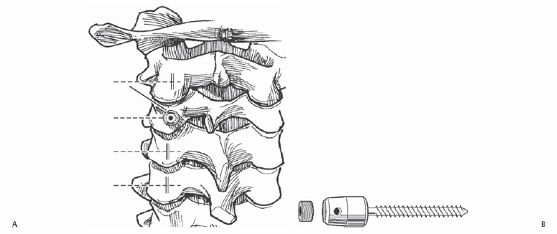
11 Yu-Po Lee, Choll W. Kim, and Steven R. Garfin To safely place screws within the cervical lateral mass while avoiding injury to the surrounding neurovascular structures. Unicortical and bicortical screws may be placed safely within the lateral masses of the cervical spine (C3–C7). Lateral mass screws and rods provide rigid segmental fixation in cases of trauma or to enhance fusions. Cervical instability, following a multilevel anterior corpectomy and strut grafting, and following posterior cervical laminectomy. Detailed preoperative imaging using plain radiographs and magnetic resonance imaging (MRI) is necessary prior to surgery to adequately assess local anatomy, including the location of neural structures and the vertebral arteries. Computed tomography (CT) is helpful in certain cases for better assessment of the bony anatomy. If the procedure is to be performed in an unstable spine, awake intubation and positioning is recommended. Electrophysiologic monitoring is also helpful. Place the patient prone in the reverse Trendelenburg position with a Mayfield pin headrest or foam pillow. The neck may need to be slightly flexed in patients with a large occiput that is preventing access to the cervical vertebrae. Avoid forceful or excessive flexion. Also, placing the head at the foot of an AMSCO table (Steris Corp., Mentor, OH) is often helpful if using fluoroscopy. Tuck in the patient’s arms at the sides. Use 3-inch tape to provide longitudinal traction to the shoulders. This aids in radiographic visualization of the cervical spine. Taking an x-ray once the patient has been positioned is helpful for checking the alignment of the cervical spine and for planning the incision. This avoids having to reposition the patient after he/she has been prepped and draped or having to enlarge the incision or violating facet joints that were not intended to be fused. The most prominent spinous processes to palpation are C2, C7, and T1. Also, C6 is the last bifid spinous process, and the vertebral arteries do not usually run in the transverse foramen of C7. Care should be taken in the exposure to stay midline in the ligamentum nuchae. Straying laterally into muscle causes bleeding that will impede visualization of the lateral masses. Care should also be taken not to dissect the muscles off of the spinous process of C2, as this could lead to potential C2-C3 instability. The drill for the lateral mass screw is aimed 15 degrees cephalad and 30 degrees laterally relative to the vertebrae. Adjustments in the position of the neck and in the table may make it difficult to judge the orientation of the vertebra. Placing a Penfield No. 4 elevator (Miltex, Tuttlingen, Germany) in the facet joint can be helpful in clarifying the orientation of the facet joint and thus the proper trajectory of the drill. Also, it is important to remember that the lateral mass of C7 is smaller and a steeper trajectory is often needed. Should lack of stable fixation become a problem with a unicortical screw, bicortical fixation may improve screw purchase. Also, a salvage screw may improve screw fixation. The most inferior screw must not violate the facet joint, as this may lead to pain at the adjacent level. Make a midline incision at the desired level. Proceed through the ligamentum nuchae to the spinous processes. Use a subperiosteal dissection to expose the posterior elements and the lateral masses. Care should be taken not to violate the facet joints that are not to be fused. The starting point for the lateral mass screws should be in the middle of the lateral mass in the cephalad-caudad plane and 1 mm medial to midline in the medial lateral plane (Fig. 11.1). Use a 2-mm pneumatic burr to penetrate the cortex. Use a 2.5-mm drill with a 14-mm stop to drill the hole. A 14-mm screw is usually sufficient for bicortical fixation. The drill should be aimed 15 degrees cephalad and 30 degrees laterally (Fig. 11.2 and Fig. 11.3). This should avoid injury to the vertebral artery, which generally lies in the midline of the lateral mass, and the nerve roots, which run inferiorly as they exit the neuroforamen. The hole depth is measured and tapped; 3.5-mm polyaxial screws with favored angles are helpful for placement of the connector rods. If bicortical fixation is desired, start with a 10-mm drill and increase 2-mm in sequential fashion until the other cortex is breached.
Cervical Lateral Mass Screw Placement (C3–C7)
Description
Key Principles
Expectations
Indications
Contraindications
Special Considerations
Special Instructions, Position, and Anesthesia
Tips, Pearls, and Lessons Learned
Difficulties Encountered
Key Procedural Steps

Stay updated, free articles. Join our Telegram channel

Full access? Get Clinical Tree


