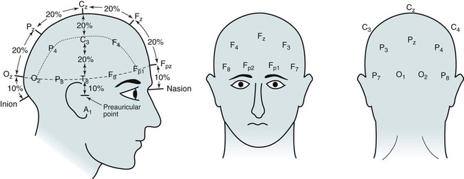
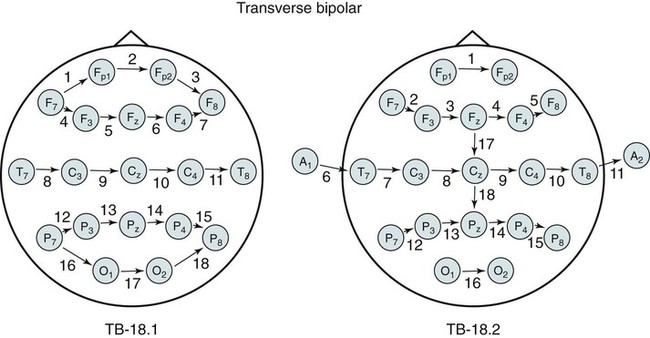
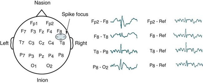
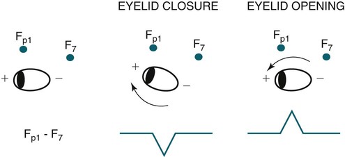
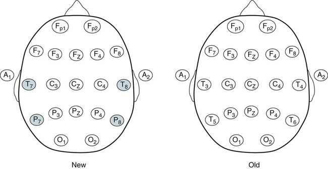
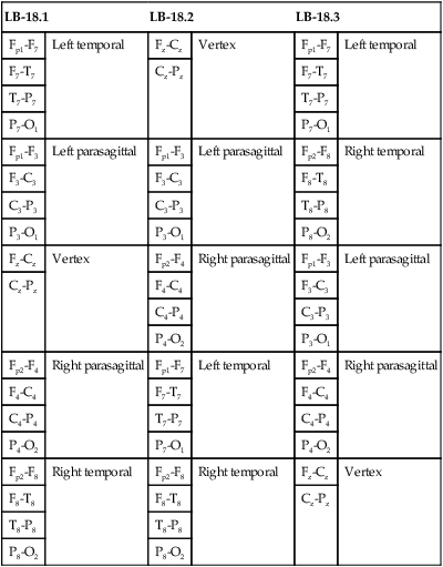
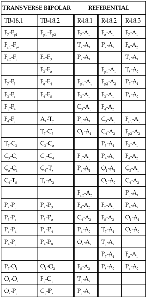
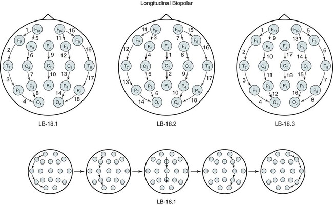
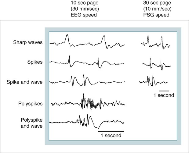
• Nocturnal epilepsy can be difficult to differentiate from parasomnias because some patients have seizures only at night, scalp EEG findings may not be visible during seizures, bizarre movements can occur during partial seizures, consciousness can be maintained, and minimal postictal confusion may be present in some cases. • NFLE manifests as three syndromes: paroxysmal arousals (mimics confusional arousals), nocturnal paroxysmal dystonia (dystonic posturing), and episodic wandering (mimics sleepwalking). The paroxysmal arousals and nocturnal paroxysmal dystonia episodes tend to be brief. • Factors favoring NFLE over a parasomnia include multiple episodes per night, stereotypical manifestations, onset out of stage N2 versus N3, and certain behaviors (e.g., cycling, fencing, pelvic thrusting) as well as immediate alertness after the episode. • In roughly 50% of the cases of NFLE, there is no abnormality in the scalp EEG during the seizure (other than artifact due to body movement). • The partial seizures of TLE are typically complex partial seizures (consciousness is impaired during the seizure). The partial seizures of FLE may be either complex or simple (no impairment of consciousness). • Seizures from the supplemental motor area may occur with intact responsiveness and no postictal confusion. Classic manifestations of seizures from the supplementary motor area include fencing with head turned away from the outstretched arm, kicking, laughing, or pelvic thrusting. Unlike psychogenic activity, there is an abrupt onset and offset. • Video PSG is essential for evaluation of patients with possible nocturnal epilepsy. A substantial number of patients with NFLE will not have either ictal or interictal EEG findings and the type of body movements (seminology) can be very helpful in arriving at a correct diagnosis. Using an extended EEG montage and visualization of waveforms in a 10-second window is recommended. • The focal seizures of FLE are more likely to occur at night than during the day. The focal seizures of TLE are more likely to occur during the day than during the night. FLE events during the day are more likely to generalize. TLE events during the night are more likely to generalize compared with those occurring during the day. • Because mastoid electrodes are fairly near the temporal lobes, interictal activity associated with TLE can often be easily seen in standard PSG montages. For example, a left temporal spike may be visible in derivations containing M1. The spike will be more prominent in C4-M1 than in C3-M2 even though the spike is on the left. • Changing to a 10-second window is essential to accurately identify interictal activity because spikes may be difficult to see in the 30-second window. It is useful to examine paroxysmal changes in EEG tracings in a 10-second window to avoid incorrectly assuming that ictal activity is an artifact. The international 10-20 system1,2 for electrode placement for electroencephalographic (EEG) monitoring is illustrated in Figure 27–1. Each electrode is represented by a letter that represents the underlying area or lobe of the brain (Fp = frontopolar; F = frontal; P = parietal; O = occipital; T = temporal) (Fig. 27–2) and numerical subscripts representing position. The odd subscripts are on the left and the even on the right, and the “z” subscripts refer to electrodes in the midline.1,2 The left and right auricular (earlobe) electrodes are A1 and A2. In sleep monitoring, these are actually placed on the mastoids and termed M1 and M2.3 Figure 27–1 illustrates the new electrode nomenclature1 in which T7, T8, P7, and P8 have replaced T3, T4, T5, and T6. In the new nomenclature, all electrodes in a given sagittal plane have the same subscript (F7, T7, P7) and most electrodes in the same coronal plane have the same letter (P7, P3, Pz, P4, P8). However, many EEG laboratories still use the old electrode nomenclature as does the majority of the published literature on epilepsy. Of note, the 10-20 electrode position2 refers to the fact that electrodes are positioned at 10% or 20% of the distance between landmarks such as nasion, inion, or the preauricular points (Fig. 27–3). A derivation is the voltage difference between electrodes: for example, Fp1-F3 is the voltage difference between electrodes Fp1 and F3. By electroencephalography (EEG) convention, if Fp1 is more negative than F3, the deflection is up.4,5 A set of derivations is called a montage. Montages are designed with a particular purpose in mind. Standard montages for sleep monitoring were illustrated in Chapter 1. Tables 27–1 and 27–2 show standard clinical EEG montages.6 Bipolar longitudinal montages (Fig. 27–4; see also Table 27–1) sequentially compare two adjacent electrodes in chains covering the head in an anteroposterior (AP) direction (“double banana”). In the most frequently used variant (LB-18.1), the chains start at the left temporal area and then progressively move toward the right. Bipolar transverse montages compare two electrodes in chains in the transverse directions (Fig. 27–5; see also Table 27–2). Referential montages compare electrodes with the ipsilateral auricular electrodes A1 and A2 (see Table 27–2). Different laboratories may display the electrodes in a given montage in different sequences. In modern digital EEG recording, all electrodes are usually recorded against a common reference. Then any two electrodes may be compared by digitally subtracting the signals (F7-ref) − (P7-ref) = F7-P7. Thus, one can change the display montage while recording or later during study review. Digital recording also allows one to visualize multiple time scales. The polysomnography (PSG) window to stage sleep is 30 seconds but the clinical EEG window is 10 seconds. The 10-second time window allows detection of brief, sharply contoured waveforms that may signify seizure activity. TABLE 27–1 Longitudinal Bipolar (AP Bipolar) 18-Channel “Double Banana” From American Clinical Neurophysiology Society: Guideline 6: a proposal for standard montages to be used in clinical EEG. J Clin Neurophysiol 2006;23:111–117. TABLE 27–2 Transverse Bipolar and Referential Montages (18 Channels) From American Clinical Neurophysiology Society: Guideline 6: a proposal for standard montages to be used in clinical EEG. J Clin Neurophysiol 2006;23:111–117. If the capacity to add a few electrodes to traditional sleep monitoring exists, one can increase the ability to detect epileptiform activity. For example, one could add two electrodes (T7, T8). The derivations F3-T7, T7-O1, F4-T8, and T8-O2 would add coverage over much of the frontal and temporal areas. These areas are the predominant foci of seizures occurring mainly during sleep. Other clinicians have utilized the addition of Fz, Cz, F7, and F8 to the usual PSG electrodes.7 The addition of synchronized digital video monitoring to nocturnal EEG or PSG recording greatly enhances the ability of the clinician to diagnose nocturnal events.8 As is discussed later, many nocturnal seizure disorders are not associated with scalp EEG findings and the patient’s actions during the seizure (seminology) may be very helpful in determining whether an episode is likely a parasomnia or nocturnal epilepsy.8 The terminology and identification of epileptic seizures and interictal activity is challenging for physicians without extensive training in EEG (Table 27–3). A transient is any isolated wave or complex that stands out compared with background activity. A spike is defined as a transient with a pointed peak and a duration of 20 to 70 msec (Fig. 27–6). On a 30-second page, spikes look like a single vertical line. A sharp wave is a transient with a deflection of 70 to 200 msec. TABLE 27–3 A spike and wave complex is a spike followed by a slow wave (usually wide and often higher amplitude). Polyspike complexes often consist of multiple spikes superimposed on a slow wave. The term epileptiform activity literally means “EEG activity resembling that found in patients with epilepsy.” This is a somewhat circular definition. Interictal activity is defined as abnormal EEG activity that occurs between seizures. Epileptiform activity includes spikes, spike and waves, and polyspike complexes. Abnormal sharp waves are also considered epileptiform or interictal activity. Of course, sharp waves can be normal (e.g., vertex sharp waves). Artifacts can sometimes mimic spikes or spikes and waves. In general, true spike and wave complexes have a “field” (Box 27–1). That is, true spike and wave activity should be seen in derivations containing several contiguous electrodes. If a spike and wave is seen only in a single derivation, the activity is usually be an artifact. Because seizures do not always appear during a given recording (see Box 27–1), the physician reading an EEG or PSG searches for spikes and/or abnormal sharp waves that may represent the interictal footprint of possible seizure activity. However, it should be noted that not all patients with spikes have seizures and not all patients with seizures have detectable interictal activity. Spikes represent abnormal brain activity that is seen as an area of negativity at the scalp. Spikes can be localized (negativity at the scalp over one area of the brain) or appear diffusely. Focal seizures usually, though not invariably, begin at the same location as the interictal spikes. The classic spike is followed by a slow wave. Although most common postictally, spike and sharp waves will occur sporadically at any time and may have a slight increase preictally. Using the usual 30-second time window, it may be difficult to appreciate spikes. A switch to a 10-second window is indicated to scrutinize any suspicious paroxysmal activity. Localized EEG waveforms (including spikes and sharp waves) will show phase reversal if the bipolar chain crosses the area of the localized EEG activity.4,5 Phase reversal does not imply an abnormal waveform. For example, K complexes and vertex sharp waves show phase reversal in montages that cross the location of origin. Phase reversal may help differentiate epileptiform activity such as a spike from artifact. Epileptiform activity is recorded as an electronegative potential. For example, in Figure 27–7A, negative spike activity is seen under electrode T7. This results in down-going deflections in F7-T7 because T7 is more negative than F7. This pattern reverses for T7-P7 because now P7 is more positive than T7. In this figure, “s” is for spike and “w” is for wave. If the spike focus is located nearly equidistant between two monitoring electrodes (F8 and T8) (see Fig. 27–7B), the derivation containing them may show little or no activity (F8-T8) and the derivations on either side will show phase reversal ([Fp2-F8] to [T8-P8]). In referential montages, a spike will have greater activity in montages containing electrodes nearer to the location of the spike. In Figure 27–8, a spike focus is located between F8 and T8. On the bipolar montage, this results in the electrical activity being nearly equal in the two electrodes, resulting in minimal activity in F8-T8 but a phase reversal in adjacent bipolar pairs. However, in referential recording, the spike results in larger and nearly equal activity in F8 and T8 with less activity in adjacent electrodes. In the usual PSG montage, electrodes are referenced to the opposite mastoid.3 Therefore, a spike located near F4 will result in greater deflection in F4-M1 compared with C4-M1 or O2-M1. It is also important to recall that the mastoid electrodes may actually be closer to spikes in the temporal area than the F4, C4, and O2 electrodes. For example, a left temporal focus of activity may be nearer M1 than F3, C3, and O1. Thus, C4-M1 will actually show more activity from a left temporal focus than C3-M2 because M1 is closer to the temporal area than C3. In the case of a left temporal spike, one would expect to see epileptiform activity in most channels referenced to the left mastoid (M1). Bell’s phenomenon describes the reflex upward movement of the front of the eyeball when the eyelids close (or blink). Because the cornea is positive with respect to the retina, this causes a deflection in derivations containing electrodes placed near the eyes (Fp1, Fp2). Recall that if G1 becomes positive with respect to G2, the derivation G1-G2 shows a downward deflection. Thus, eyelid closure results in downward deflections in Fp1-F7 and Fp2-F8. This is illustrated in Figures 27–9 to 27–11.
Clinical Electroencephalography and Nocturnal Epilepsy
Electroencephalographic Monitoring

Bipolar Monitoring and Standard Montages
LB-18.1
LB-18.2
LB-18.3
Fp1-F7
Left temporal
Fz-Cz
Vertex
Fp1-F7
Left temporal
F7-T7
Cz-Pz
F7-T7
T7-P7
T7-P7
P7-O1
P7-O1
Fp1-F3
Left parasagittal
Fp1-F3
Left parasagittal
Fp2-F8
Right temporal
F3-C3
F3-C3
F8-T8
C3-P3
C3-P3
T8-P8
P3-O1
P3-O1
P8-O2
Fz-Cz
Vertex
Fp2-F4
Right parasagittal
Fp1-F3
Left parasagittal
Cz-Pz
F4-C4
F3-C3
C4-P4
C3-P3
P4-O2
P3-O1
Fp2-F4
Right parasagittal
Fp1-F7
Left temporal
Fp2-F4
Right parasagittal
F4-C4
F7-T7
F4-C4
C4-P4
T7-P7
C4-P4
P4-O2
P7-O1
P4-O2
Fp2-F8
Right temporal
Fp2-F8
Right temporal
Fz-Cz
Vertex
F8-T8
F8-T8
Cz-Pz
T8-P8
T8-P8
P8-O2
P8-O2
TRANSVERSE BIPOLAR
REFERENTIAL
TB-18.1
TB-18.2
R-18.1
R-18.2
R-18.3
F7-Fp1
Fp1-Fp2
F7-A1
Fz-A1
F7-A1
Fp1-Fp2
T7-A1
Pz-A2
F8-A2
Fp2-F8
F7-F3
P7-A1
T7-A1
F3-Fz
Fp1-A1
T8-A2
F7-F3
Fz-F4
Fp1-A1
Fp2-A2
P7-A1
F3-Fz
F4-F8
F3-A1
F3-A1
P8-A2
Fz-F4
C3-A1
F4-A2
F4-F8
A1-T7
P3-A1
C3-A1
Fp1-A1
T7-C3
O1-A1
C4-A2
Fp2-A2
T7-C3
C3-Cz
P3-A1
F3-A1
C3-Cz
Cz-C4
Fz-A1
P4-A2
F4-A2
Cz-C4
C4-T8
Pz-A1
O1-A1
C3-A1
C4-T8
T8-A2
O2-A2
C4-A2
Fp2-A2
P3-A1
P7-P3
P7-P3
F4-A2
F7-A1
P4-A2
P3-Pz
P3-Pz
C4-A2
F8-A2
O1-A1
Pz-P4
Pz-P4
P4-A2
T7-A1
O2-A2
P4-P8
P4-P8
O2-A2
T8-A2
P7-A1
Fz-A1
P7-O1
O1-O2
F8-A2
P8-A2
Pz-A2
O1-O2
Fz-Cz
T8-A2
O2-P8
Cz-Pz
P8-A2
Waveform and Seizure Terminology
Spike
Transient with a pointed peak and duration of 20–70 msec
Polyspike
Transient with multiple spikes
Sharp wave
Transient with a pointed peak and duration of 70–200 msec
Interictal discharge
Abnormal (epileptiform) EEG activity that occurs between seizures
Spike and wave
Spike followed by a slow wave
Ictal activity
EEG correlate of a seizure
Phase Reversal

Localization in Referential and PSG Montages
Normal Sleep Waveforms in the 10-Second Window
Eye Movements and Bell’s Phenomenon
![]()
Stay updated, free articles. Join our Telegram channel

Full access? Get Clinical Tree


Clinical Electroencephalography and Nocturnal Epilepsy

