Disc Replacement Technologies in the Cervical and Lumbar Spine

Chapter 154 Disc Replacement Technologies in the Cervical and Lumbar Spine


Background Considerations


Although great progress has occurred on the biomechanical aspects and significant progress on the clinical aspects of spinal arthroplasty, it should still be considered a work in progress. Surgeons should not forget that there are very acceptable alternatives to arthroplasty within the surgical armamentarium and should feel no compulsion to undertake the latest techniques.


The intervertebral disc is composed of a central nucleus pulposus (containing predominantly Type 1 collagen fibrils) and a peripheral annulus fibrosis (which can consist of up to 25 lamellae of mostly Type 1 collagen) that provides support, allows some movement, resists excessive movement, and, according to some absorbs shock.1 The ability to resist axial stresses is considerable but decreases with age.2 With normal loading, the normal nucleus pulposus is transposed by vertebral body pressure to tighten the annulus and produce ligamentous intervertebral stability. With heavy loading, the rigid, spherical normal nucleus pulposus gains stable seating in the nuclear recesses, where it acts as a piston to depress the cribriform plates, bend the trabeculae, and produce the necessary stability. With return of normal loading, the vertebral body rebounds, the nucleus pulposus resumes its normal locus, and the annulus tightens. Therefore it has been recognized that the vertebral bodies are very significant contributors to the shock-absorption function of the spinal column.3


It is fairly well accepted that the degenerative changes that result from aging of the vertebral body, the annulus fibrosis, and the nucleus pulposus are likely to begin with infarction of the cribriform cartilage endplates and subsequent nutritional failure of the nucleus pulposus.4 Calcification of the endplates occurs in adulthood, and the nutrient uptake and waste elimination within the disc then becomes dependent on diffusion. This leads to anaerobic metabolism’s taking a more prominent role, leading to lactate production and an acidic environment. The proteinases become more active, resulting in further disc degeneration.5 Indeed, it has been shown that when heavy loads are applied to the intervertebral disc, the normal disc biology can be disrupted, leading to an increase in catabolic enzymes and an acceleration of intervertebral disc degeneration.6 Studies have noted increased rates of degenerative disc disease in siblings of affected persons and strong correlation in twins.


The pathophysiology of the degenerative disease process has been described by Kirkaldy-Willis.7 The progressive disease is divided into three stages based on the amount of damage or degeneration to the disc and facet joints at a given point in time. However, the cascade of individual motion segment degeneration is best thought of as a continuous process rather than as three clearly definable and separate stages.


Stage 3: Stabilization


The third stage is described as the stabilization stage. It is exemplified by end-stage tissue damage and attempts at repair. Further nucleus pulposus resorption occurs with increasing intervertebral disc space narrowing fibrosis, endplate irregularities, and the formation of osteophytes. The stage typically occurs later and in the lumbar spine can manifest with symptoms of neurogenic claudication or radiculopathy from any combination of central, lateral recess, or foraminal stenosis. At this stage the lower limb symptoms can prevail over low back pain.


However, MRI is positive in asymptomatic patients at least 40% of the time.814 About 30% of adults without low back pain have evidence of protruded disc on MRI; more than half have bulging or degenerative discs and a fifth have annular fissures.15 Therefore, the relationship among disc degeneration, the MRI appearance, and spine-related pain remains controversial, and the decision to undertake surgical management of a degenerative spinal condition is a large one and is very much patient specific. The presurgical workup must include a thorough history relating to any spinal complaints including neurologic compromise, a diligent physical examination that leads to a working diagnosis, and the appropriate subsequent confirmatory radiologic imaging. Although simple radiography is an inexpensive and readily accessible starting point, its utility is severely limited by its inability to visualize neural structures directly or indirectly, and therefore the presence or absence of neural compression is indeterminable.16,17 Nonetheless, all our potential arthroplasty patients undergo plain flexion-extension radiographs of the appropriate spinal segment to look for instability of the potential operative or another segment and to confirm that there is still movement of the proposed operative segment. Also, if there is going to be any delay in obtaining true confirmatory imaging, routine spinal radiography should be undertaken to exclude other disease processes, such as malignancy, infection, or arthritis. Interestingly, when Friedenberg and Miller compared 92 asymptomatic patients with those complaining of neck and arm pain, no difference was found between the two groups in radiographic findings, with the exception of a greater incidence of disc degeneration at C5–6 and at C6–7 in the symptomatic group.18


All patients undergo MRI of the appropriate spinal area unless a contraindication exists. Virtually all patients now undergo supplementary computed tomography (CT) scanning, which allows excellent visualization of bony osteophytes and the foraminal architecture including the facet joints, especially with the reconstructed (3D) CT imaging. CT scanning in flexion and extension can allow an enhanced appreciation of subtle instability or spinal canal or foraminal encroachment (especially by the ligamentum flavum if CT myelography is undertaken). The CT imaging also allows the surgeon to assess the disc size before surgery.


Electromyography (EMG) and nerve conduction studies can be useful in diagnostic evaluation, providing additional objective evidence of root compression in patients with relatively minor neurologic findings. Moreover, they are useful in differentiating root, plexus, peripheral nerve, and muscle disorders that might mimic cervical or lumbar radiculopathy. They can also help to uncover a second problem that coexists with the radiculopathy, such as carpal tunnel syndrome, ulnar neuropathy, or compression of the lateral cutaneous nerve of the thigh causing meralgia paresthetica.


We also occasionally request the radiologists to undertake a provocative discogram, which should include a normal control level above or below the degenerative disc in question.


None of our groups have been provided with the resources to undertake psychological profiling of prospective patients.19 Nonetheless, we try to avoid operating on patients with outstanding litigation claims.


General Considerations


The elimination of motion at the functional spinal unit (two vertebral bodies, the intervertebral disc, and associated facet joints) has been the mainstay of treatment since the 1960s.26 Anterior cervical discectomy and fusion is the standard of care for relief of pain and stabilization associated with radiculopathy and myelopathy,27 with excellent long-term results. However, lest we forget, very satisfactory results have been reported with the placement of nothing at all in the disc space after anterior cervical discectomy.28,29 It was the significant concerns raised by Hillibrand30,31 and others who noted, in various series of patients who had undergone anterior cervical arthrodesis, that between 25% and 89% who were followed for a lengthy period developed new degenerative changes at adjacent levels.


The debate is complex because much of the biomechanical and clinical evidence about the cause of adjacent segment disease is anecdotal and inconsistent.32 Although intradiscal pressure and motion alterations have been found at the adjacent levels following a single-level anterior lumbar interbody fusion (ALIF) in a calf model,33 it is recognized that longer fusions, both in the lumbar spine and in the cervical spine, have not been associated with higher rates of adjacent segment disease.32,34


Indeed, the recent enthusiasm for the application of cervical plates to aid fusion might actually be related to the increase in adjacent segment degeneration. Anterior plate impingement upon an adjacent disc is likely to accelerate adjacent level changes.35 An association between adjacent level ossification and the plate-to-disc distance has been established in a retrospective review of 118 patients undergoing anterior cervical discectomy and fusion.34 We should not forget that a patient who has already developed cervical spondylosis at the most common level (C5–6) to such a degree that surgery is warranted may be predisposed to develop degeneration at an adjacent level (C6–7 or C4–5) because of the natural history of the spondylosis and independent of whether or not a fusion is performed at the original level.


Moreover, despite the frequent reference to Hillibrand’s paper30 by those promoting arthroplasty, the authors later indicated that the paper suggested that the development of adjacent segment disease may be related to the natural history of cervical spondylosis.31 Similar findings have been documented in the lumbar spine by Ghiselli and colleagues,33 who found no correlation between the length of fusion and the rate of reoperation in 215 patients following posterior lumbar fusion. They noted that segments that were adjacent to a single-level fusion had a three times higher risk for developing disease than did those adjacent to a multiple-level fusion.


Contraindications to cervical disc replacement include ankylosing spondylitis, rheumatoid arthritis, a history or cervical infection, ossification of the posterior longitudinal ligament, and diffuse idiopathic skeletal hyperostosis. We avoid an arthroplasty in the presence of severe spondylosis at the proposed level (significant or bridging osteophytes, disc height loss of greater than 70%, absence of motion). Similarly, radiologic suggestion of cervical instability including translation of more than 3 mm or more than 11 degrees of rotational difference to that of either adjacent level is a contraindication. We would be very reluctant to undertake an arthroplasty in a morbidly obese patient (body mass index [BMI] >40) or in insulin-dependent diabetic patients (for fear of infection). At present we will not consider an arthroplasty for treatment of isolated axial neck pain. Clearly, allergy to any of the components of the implant is a definite contraindication.


Operative Procedure


ProDisc-C Artificial Cervical Disc Placement


The procedure is undertaken under general anesthesia with the patient supine and the cervical spine in the neutral or very minimally extended position. Hyperextension of the neck is avoided, not least because it then requires greater force to retract the pharynx and larynx to expose the anterior cervical spine. We simply place a 1-liter saline bag between the shoulders and the head in a head ring. The head should also be strapped to keep the head and neck stable during various steps of inserting the ProDisc-C implant (Synthes, West Chester, PA).


The endotracheal tube is carefully secured and passes superiorly over the head out of the way of the surgeon and assistant. Routinely, a collar incision is used, preferably placed in a skin crease or along a Langer line. It is technically easier for a right-handed surgeon using the high-speed air drill under the microscope to operate from the right side. The risk of injury to the recurrent laryngeal might be higher on the right, but the risk to the thoracic duct is diminished. The position of the incision is important. We usually perform lateral screening with a metallic marker before marking and draping. Usually an incision at the upper level of the cricoid cartilage exposes C5–6, and an incision just below the level of the cricoid suffices for C6–7 exposure.


The skin incision is taken to the platysma, which we sometimes split rather than cut in the line of the incision. Undercutting the subcutaneous tissues facilitates this approach, which is rewarded with an excellent postoperative cosmetic result. The investing cervical fascia is divided along the anterior border of the sternomastoid muscle to define the plane between the carotid sheath laterally and the larynx, trachea, and esophagus medially. The superior belly of the omohyoid muscle is identified passing from the hyoid bone inferolaterally. Generally it is possible to divide the fascia around this and gently retract it up or down, but occasionally it is necessary to divide it usually at its midtendinous segment. During the preliminary dissection it is essential to feel the pulsation of the carotid sheath laterally and to continue dissection in a posteromedial direction toward the spine.


The anterior cervical spine is initially palpated after gentle retraction of the esophagus and trachea using a Langenbeck retractor. Occasionally a prominent osteophyte at the disc level aids in identifying the level. The prevertebral fascia is divided in the midline. Although this plane of dissection is usually bloodless, small draining veins might require bipolar diathermy and division. It is rare for the superior thyroid artery to cross the path of surgery. It can be wise to ligature the artery formally if it is to be divided. We make no effort to identify the recurrent laryngeal nerve. We have found that it readily mobilizes along with the trachea and esophagus from the midline to the opposite side.


The prevertebral fascia is reflected laterally below the longus colli muscle. Careful incision of the medial aspect of the muscle with cutting diathermy (appropriately sheathed, thereby only exposing the very tip) on a low setting is helpful in elevating the longus colli muscle. At this stage, the disc level is formally identified with a cross-table lateral fluoroscopic image using an image intensifier. The marking needle is bent so that it can only be placed in the anterior portion of the disc. The needle is withdrawn and a small piece of the center of the disc is cut out. This action ensures no later mistakes in recognizing the correct level.


Our groups have used four different arthroplasty devices. We describe the ProDisc-C simply as an illustrative example.


For the insertion of the ProDisc-C implant, once the correct level has been identified, the midline is marked before dissecting off the longus colli muscles. The presence of longus colli muscles on either side is an excellent reference point for marking the midline, which is essential for correct placement of the ProDisc-C prosthesis (one keel). It is recommended to identify the midline using an anteroposterior (AP) projection. Once the midline is marked, the longus colli muscles are dissected off the vertebrae using either low-current monopolar diathermy or high-current bipolar diathermy.


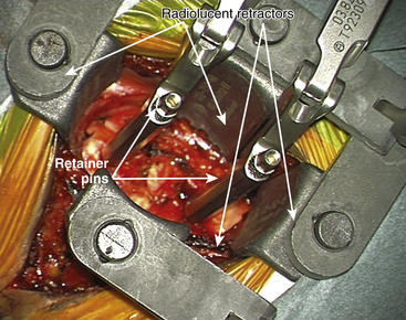
Special radiolucent retractors are applied under the longus colli muscles to prevent injury to the sympathetic chain, carotid arteries, and the midline structures.


For placement of the implant it is essential to have radiolucent retractors because the procedure require visualization of most steps on x-ray.


The ProDisc-C artificial cervical disc system comes with vertebral body retainer screws. The retainer screws are inserted under x-ray guidance (lateral projection) in the upper one third of the superior vertebra and inferior one third of the inferior vertebra parallel to the respective end plates (Fig. 154-1). The screws are bicortical. The length of the screws can be calculated on the picture archiving and communication system (PACS) using a CT scan image. The retainer handle is mounted onto the screws. It is important to leave enough space between the retainer pins to allow for the height of the keel on the ProDisc-C prosthesis. It is important not to use the retainer pins to distract the disc space. Their purpose is to stabilize the segment while the various steps of preparing the bed for the implant, keel cutting, and insertion of the implant are carried out.


Once the retainer pins are in place, discectomy is carried out under microscope. Anterior osteophytes overlying the disc space are removed using a rongeur or the high-speed drill to flatten the surface.


The primary objective of the operation is the decompression of the spinal canal and/or foramina. The annulus is incised and removed with a pituitary rongeur or curette. The disc can be removed with curettes or a high speed drill (Fig. 154-2). Good lateral exposure is necessary for the implant, and the dissection is continued laterally until the upslope of the uncovertebral joints on either side is identified. Further lateral dissection or drilling can damage the vertebral arteries. The uncovertebral joints must not be drilled to keep the segment stable after the insertion of the ProDisc-C implant.
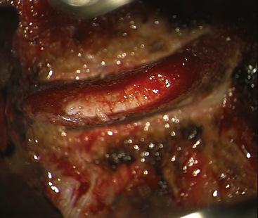


The operating microscope is introduced once most of the disc space has been cleared. The high-speed drill is used to remove the remaining cartilaginous end-plate and annulus. Discs with plenty of bony spondylosis are not ideal candidates for replacement, and fusion is a preferred option. Posterior osteophytes are drilled using spherical burs of appropriate size. Downward pressure is never applied to the drill head; instead, the drill is stroked in an axial plane parallel to the endplate. Posterior osteophytes can be thinned out by the drill and then gently cracked off with a small curette or 1-mm Kerrison upcutting rongeur. The use of bone wax for vertebral bleeding should be kept to an absolute minimum because it will hinder osteointegration of the implant prosthesis.


During the entire procedure the risk to three important structures—the spinal cord and the right and left vertebral arteries—must be considered. In severely spondylotic spines it is possible to be skewed to one side early in the procedure. It is always imperative to remain aware of the midline. Once the posterior osteophytes are removed, the annulus is nibbled with a 1-mm or 2-mm shallow-footplate Kerrison punch. This step can be tedious when the tissues are grossly thickened and degenerate. The posterior longitudinal ligament is teased open with a blunt hook and a sickle-shaped knife (Karlin knife). It is then removed with a small upcutting punch. Because an arthroplasty is to be performed, it is imperative to formally remove all the posterior osteophytes. Indeed, excessive osteophytes may be a contraindication to an arthroplasty. Exposure of the dura is the confirmation of adequate decompression. Careful exploration with a small blunt probe alongside the root foramen allows confirmation that the root is free.


The endplates are then prepared. To achieve the requisite bone-prosthetic contact, it is important to make the endplates as flat as possible within the footprint of the implant, while maintaining the integrity and strength of the bony vertebral endplates. Care must be taken not to compromise the endplate’s strength by removing too much cortical bone. Trial sizes of the arthroplasty implant are selected.


The goal is to select the largest footprint possible and the smallest height necessary. The implant should cover the majority of the vertebral body endplate. The undersized implant leads to increased risk of implant subsidence.


Connect the trial handle to the trial implant. Ensure that the stop is fully screwed, closest to the footprint. Align the trail implant on the midline and advance the trial implant under image intensifier into the disc space.


The optimal position of the trial implant is at the posterior margin of the vertebral bodies, centered on the midline. If the stop does not allow the trial implant to enter deep enough, the implant can be positioned deeper by turning the adjustable stop anticlockwise (1 revolution = 0.5 mm).


Release the distraction to determine the optimal height of the trial implant. The height should be the smallest appropriate height to match normal adjacent discs.


Ensure that the trial stop is fully seated against the vertebral bodies, apply mild compression with vertebral body retainer, and remove the handle from the trial implant. Check the position of the implant in lateral view.


A double shadow on the lateral view means that the trial implant is not positioned straight in the sagittal plane.


Disc trials are supplied in sizes corresponding to each prosthetic footprint and height. Six different footprints are available for optimal coverage of the vertebral end plate. M is 15 mm wide and 12 mm deep, MD is 15 mm wide and 14 mm deep, L is 17 mm wide and 14 mm deep, LD is 17 mm wide and 16 mm deep, XL is 19 mm wide and 16 mm deep, and XLD is 19 mm wide and 18 mm deep.


Using fluoroscopy, surface apposition at the bone-implant interface of the trial can be verified and the implant height can be compared with adjacent discs to reduce the risk of overdistraction. The artificial disc inserter, which holds the implant, is used to correctly place the disc exactly in the midline (as indicated by the vertebral distractor pins). Fluoroscopy monitors the depth within the disc space.


Selecting an implant that is too tall can limit segmental range of motion. Our clinical experience that in approximately 80% of all cases the correct trial implant has a height of 5 mm.


Milling for Keel Cut Preparation


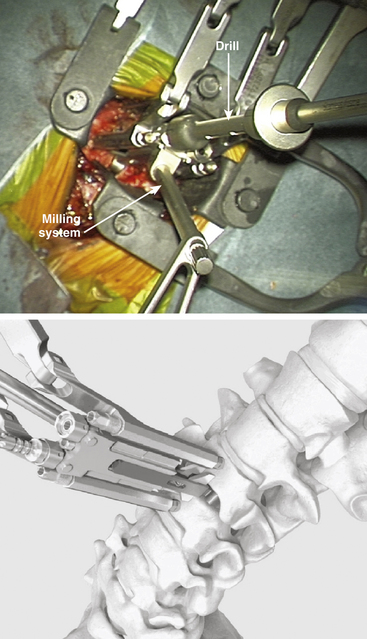
Choose the milling guide according to the height of the trial implant (Fig. 154-3). Slide the milling guide over the shaft of the trial implant and tighten the locking nut. Verify that the milling guide is centered on the midline. To ensure construct stability, place the sharp orientation pin through the superior hole in the milling guide and manually drive it into the bone under fluoroscopy control (Fig. 154-4).

< div class='tao-gold-member'>

Stay updated, free articles. Join our Telegram channel

Jul 16, 2016 | Posted by in NEUROSURGERY | Comments Off on Disc Replacement Technologies in the Cervical and Lumbar Spine

Full access? Get Clinical Tree

Get Clinical Tree app for offline access