29 Endoscopic Anatomy of the Clivus and Posterior Fossa
Luigi Maria Cavallo, Isabella Esposito, Matteo De Notaris, Felice Esposito, Manfred Tschabitscher, and Paolo Cappabianca
 Introduction
The idea driving the evolution of skull base surgery is the creation of surgical corridors molded on the three-dimensional orientation of the main neurovascular structures. The part of the ventral skull base extended from the retrosellar area to the upper cervical spine has been exposed through several anterior, anterolateral, and posterolateral routes,1–5 performed with conventional or keyhole exposure,6 or with microsurgical,7 endoscope-assisted or pure endoscopic techniques.8–11 Such variety of surgical strategies corresponds to the challenging complex anatomy of this region.
Because the lesions arising in the midline posterior skull base often displace the neurovascular structures dorsally and laterally, an anterior surgical window through the natural endonasal corridor is attractive and the endoscopic technique provides a dynamic close-up view of such deep areas and of the neurovascular structures bordering the surgical corridors itself.
The endoscopic endonasal approach enables access to the entire sphenoid, clivus, and craniovertebral junction; this route has been used for the management of either extradural or intradural lesions from the retrosellar area down to the craniovertebral junction.10,12–22
The main preconditions for using this technique are multidisciplinary cooperation,23 thorough anatomic knowledge,24,25 advanced surgical skills,26,27 and familiarity with state-of-theart imaging techniques, dedicated surgical instruments, and reconstruction strategies and materials.28 Cadaver-laboratory endoscopic dissections represent the first step in improving the surgeon’s orientation and self-confidence; such exercises are mandatory to understand the anatomy of the skull base and to acquire a three-dimensional orientation, which will be of value also when unlocking the posterior cranial fossa through lateral and posterior routes.
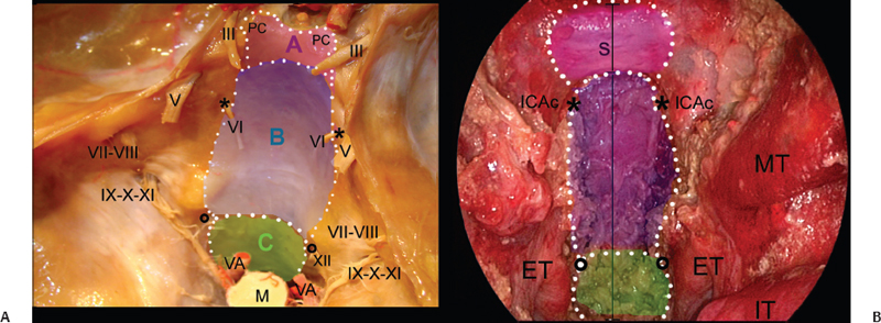
This chapter describes the endoscopic endonasal approach to the posterior cranial fossa and highlights the main anatomic relationships and potential problems of the technique. To simplify the anatomic description, we divide the posterior skull base into three levels (Fig. 29.1):
• Cranial: from the posterior interclinoid line to the floor of the sella turcica, which corresponds to the retrosellar area
• Middle: from the floor of the sella turcica to the line connecting the hypoglossal canals
• Caudal: at level of the craniovertebral junction
The measures reported in this chapter derive from several anatomic studies.24 However, they are highly variable, as demonstrated by the wide standard deviations reported in the original papers. Furthermore, to improve the incisiveness of the anatomic description, we have omitted the analysis of many important anatomic variations; nevertheless, the surgeon must have thorough knowledge about these variations before applying this technique on patients.

Fig. 29.1 Transcranial (A) and endoscopic endonasal (B) views of the midline posterior cranial base. The overlapped drawing shows the extension of the bone window during the endoscopic endonasal approach to the posterior skull base. The dotted lines border the surgical windows to expose the retrosellar area (pink area, A), retroclival area (blue area, B), and craniovertebral junction (green area, C). ET: eustachian tube; ICAc: paraclival segment of the internal carotid artery; IT: inferior turbinate; M: medulla; MT: middle turbinate; PC: posterior clinoid; S: sella; VA: vertebral artery; *: Dorello’s point; circle: hypoglossal canal; black line: midline. Nerves: III: oculomotor nerve; V: trigeminal nerve; VI: abducens nerve; VII-VIII: acoustic-facial bundle; IX-X-XI: lower cranial nerves; XII: hypoglossal nerve.
 Imaging Techniques
Recent advances in three-dimensional reconstruction techniques and measurement software have greatly improved the surgeon’s ability to perform detailed preoperative planning.29,30 State-of-the-art imaging technologies (Amira¯ Visage Imaging Inc., San Diego; Osirix¯, Advanced Open-Source PACS Workstation DICOM viewer) permit the study of the individual anatomy, thus spurring the virtual reality of the imaging to be part of the preoperative workup.
High-resolution computed tomography scan with coronal and sagittal reconstruction and both soft tissues and bone algorithms addresses the paranasal sinuses, skull base foramina, and canals. In particular, the following points should be assessed in determining the feasibility of the approach:
• Pneumatization of the sphenoid sinus: in a conchal-type sphenoid sinus, the clival indentation below the sella is not visible; sphenoidal and rhinopharyngeal segments of the clivus are not clearly identified, which makes the exposure more difficult
• Bone dehiscence at the level of both parasellar and paraclival carotid prominences
• Vidian canal on axial and coronal images and its relation to the foramen lacerum
• Carotid canal
• Configuration of the posterior clinoids
• Configuration of the craniovertebral junction
Magnetic resonance imaging is complementary to computed tomography, but it is unable to delineate the fine osseous details required for endoscopic skull base surgery; the examination is performed in the axial, coronal, and sagittal planes with 3-mm sections. The comparison between a T2-weighted image, a T1-weighted image, and contrast-enhanced T1-weighted images enables assessment of either normal anatomy or pathology of the skull base. Inflammatory tissue and fluid in the paranasal sinuses can be separated from tumoral tissue with the T2-weighted image. Fat-saturation T1-weighted sequences reduce misinterpretation of signal from adipose tissue. They are mandatory to evaluate the parapharyngeal space adjacent to the skull base; the exit foramina of the cranial nerves, which contain fatty tissue; and recurrent skull base lesions. These sequences also improve the definition of clival pathology because it contains bone marrow. The internal carotid artery and the other vascular structures are better defined by magnetic resonance angiography and digital subtraction angiography; this latest is the best method to delineate the vascular supply of a specific anatomical area or lesion; however, it rarely has a diagnostic value and its main indication is preoperative tumor endovascular embolization.
 Endoscopic Endonasal Approach
According to the guidelines highlighted by the creation of the endonasal corridor for an extended endoscopic endonasal approach to the skull base and namely to the clival area requires the following steps:
• Removal of one middle turbinate, usually the right one; the other middle turbinate is pushed laterally
• Middle meatal antrostomy preserving the uncinate process and extending inferiorly as necessary, on the side where the middle turbinate has been removed
• Creation of a pedicled nasoseptal flap on the septal branch of the right sphenopalatine artery, which is positioned into the maxillary sinus through the created antrostomy; this flap is used to reconstruct the surgical access in the multilayered reconstruction
• Detachment of the nasal septum from the sphenoid keel and removal of its posterior part (approximately 2 cm) to widen the working corridor
• Posterior or total bilateral ethmoidectomy, as necessary
• Wide anterior sphenoidotomy (taking care of the posterior nasal artery)
• Removal of the intrasphenoidal septa, with flattening the whole sphenoid wall to better host the nasoseptal flap for the reconstruction
• Identification of sphenoidal bony landmarks—sella, planum sphenoidale, medial and lateral opto-carotid recesses, and clival indentation—could help the surgeon’s orientation
At this point two surgical corridors can be used, one above and the other below the inferior wall of the sphenoid sinus. The superior corridor leads to the sellar area and to the sphenoidal portion of the clivus. The inferior corridor leads to the rhinopharyngeal segment of the clivus, the foramen magnum, and craniovertebral junction.
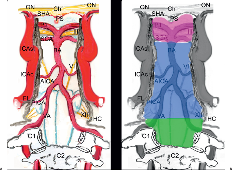
As stated above, we divide the posterior cranial fossa in three levels (Fig. 29.2). This conceptual classification was inspired by the neurovascular structures bordering the surgical window, and for each level we will describe the exposure and the intradural exploration.
The main steps to expose the retrosellar area (cranial level of the posterior skull base) are as follows:
• Opening of the sella and the tuberculum sellae
• Removal of the medial opto-carotid recess and the sellar floor
• Identification of the superior and inferior hypophyseal arteries
• Mobilization of the gland17
• Drilling of the sellar floor and dorsum sellae
• Removal of the posterior clinoids

Fig. 29.2 Schematic drawings showing the intradural neurovascular structures exposed through the endonasal route (A) and the borders of the three surgical windows (retrosellar, retroclival, and craniovertebral junction) (B). C1: atlas; C2: epistropheus; Ch: chiasm; FL: foramen lacerum; HC: hypoglossal canal; ICAc: paraclival segment of the internal carotid artery; ICAs: parasellar segment of the internal carotid artery; ON: optic nerve; P1: precommunicating segment of the posterior cerebral artery; PICA: posterior inferior cerebellar artery; PS: pituitary stalk; SCA: superior cerebellar artery; VA: vertebral artery; pink area: cranial level; blue area: middle level; green area: caudal level. Nerves: III: oculomotor nerve; VI: abducens nerve; XII: hypoglossal nerve.
The parasellar segment of the internal carotid artery borders laterally the surgical corridor; “kissing carotid arteries” should be ruled out preoperatively and are a contraindication to the transdorsum exposure of the retrosellar area.
Depending on the superior extension of the area to be exposed, the gland can be mobilized on one side or reflected upward. The Pittsburgh group has applied an en-bloc transposition technique.17 This technique requires complete disconnection of the gland from the pituitary fossa, which is obtained by cutting the ligaments that anchor the capsule to the medial wall of the cavernous. The neurohypophysis, which has a jelly-like appearance, is more firmly attached posteriorly and should be detached sharply. During this last maneuver, overpressure of the dissector should be avoided because a certain degree of dehiscence of the dorsum can be found. Furthermore, a persistent trigeminal artery may be located just posterior to the neurohypophysis; in fact, such a vessel can leave the cavernous sinus through either the dorsum or the dura lateral to it. During such maneuvers, the hypophyseal cistern should be preserved; in elderly patients it may become larger and extend laterally or to the neurohypophysis. These arachnoidal diverticula can be dissected and fixed out from the surgical corridor with a few drops of fibrin glue. The same technique can be used to fix the gland after its dislocation. The critical point of this step is avoiding stretching the pituitary stalk and the subsequent possible wallerian degeneration of the hypothalamic neurons.
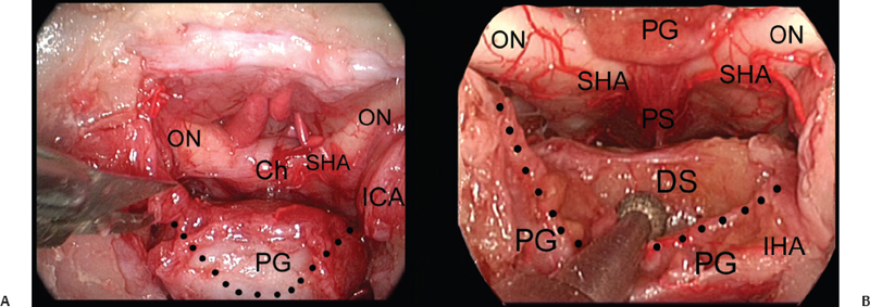
In our dissection, selective dislocation of the central part of the gland could be obtained with a V-shaped cut; the lateral parts of the gland are left in place (Fig. 29.3). This strategy may reduce the length of this step and the stretching of the infundibulum.
These techniques need larger surgical series before being validated as standard procedures and are controversial, especially in the case of purely retrosellar lesions that do not alter the pituitary function.
Drilling of the sellar floor enhances the working area before starting the transdorsum approach and provides a certain degree of pituitary mobility, which could be enough when exposing of the prepontine cistern.
During the drilling of the dorsum sellae, the working area is funnel-shaped because the intercarotid distance at the anterior wall of the sella is approximately 20 mm24 whereas the posterior interclinoidal distance is approximately 15 mm24; this places the neurovascular structures into the parasellar area at risk of injury.
Furthermore, the lateral surface of the sella should be inspected for the presence of sellar bridges, which are bands of bone running between the anterior and posterior clinoids and should be fractured carefully before removal of the posterior clinoids.
The removal of both sphenoidal and rhinopharyngeal segments of the clivus exposes the middle level of the posterior skull base, through the following steps (Fig. 29.4)8:
• Identification, in a medial to lateral direction, of the vomer-sphenoid junction, the anterior foramen of the palatovaginal canal, and the pterygoid canal. The vaginal process of the medial pterygoid plate has a groove on its inferior surface that articulates with the sphenoidal process of the palatine bone, thus forming the palatovaginal canal (or pharyngeal canal) (Fig. 29.4A,B), which opens into the pterygopalatine fossa and carries the pharyngeal nerve and artery.
• Removal of the vomer and drilling of the inferior wall of the sphenoid sinus. The lateral extension of bone removal is limited by the pterygoid canal. It runs through the inferior wall of the sphenoid sinus, toward the anterior genu of the petrous segment of the internal carotid artery (ICA).31 This canal can be localized 0.5 cm laterally to the vomero-sphenoid junction.32 By drilling the bone inferomedially to this canal, the surgical corridor can be widened while reducing the risk of tearing the ICA (Fig. 29.4C).
• Dissection of the rhinopharyngeal mucosa and lateralization of the longus capitis and longus colli muscles
• Identification of the foramen magnum and hypoglossal canals
• Drilling of the clival bone

Fig. 29.3 (A,B) Exposure of the upper clivus (cranial level) realized through an upward transposition of the pituitary gland. Ch: chiasm; DS: dorsum sellae; ICA: internal carotid artery; IHA: inferior hypophyseal artery; ON: optic nerve; PG: pituitary gland; PS: pituitary stalk; SHA: superior hypophyseal artery; dotted line: borders of the transglandular transposition.
Stay updated, free articles. Join our Telegram channel

Full access? Get Clinical Tree


