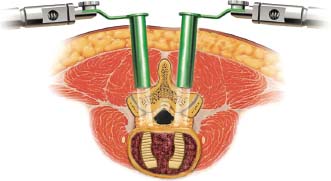
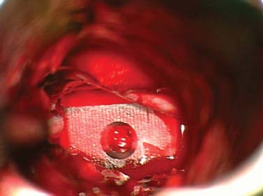
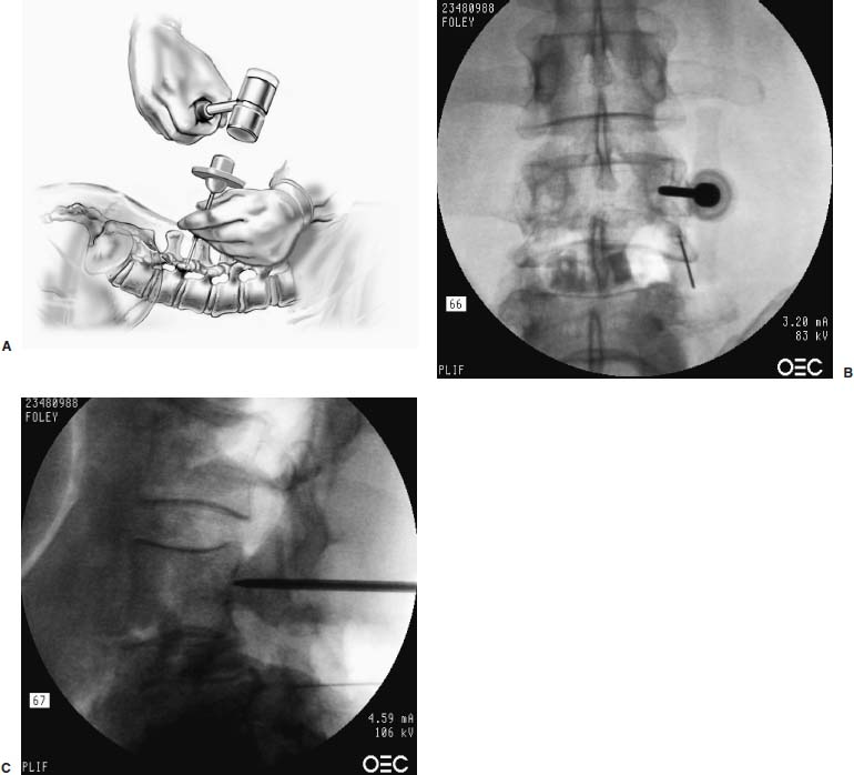
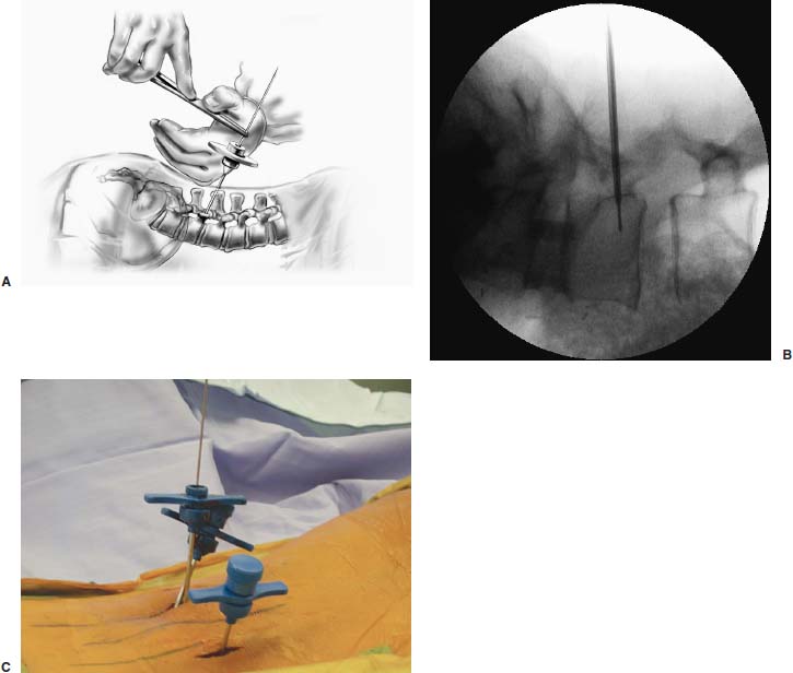
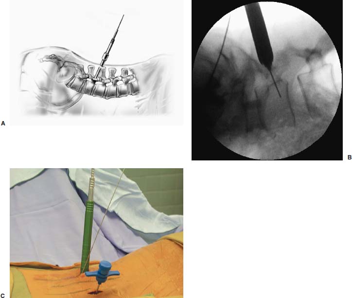
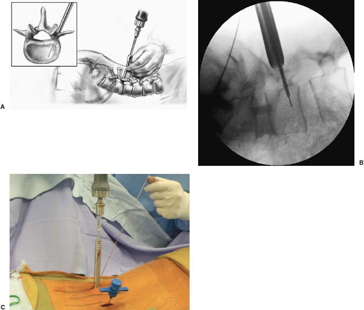
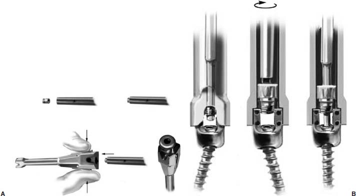
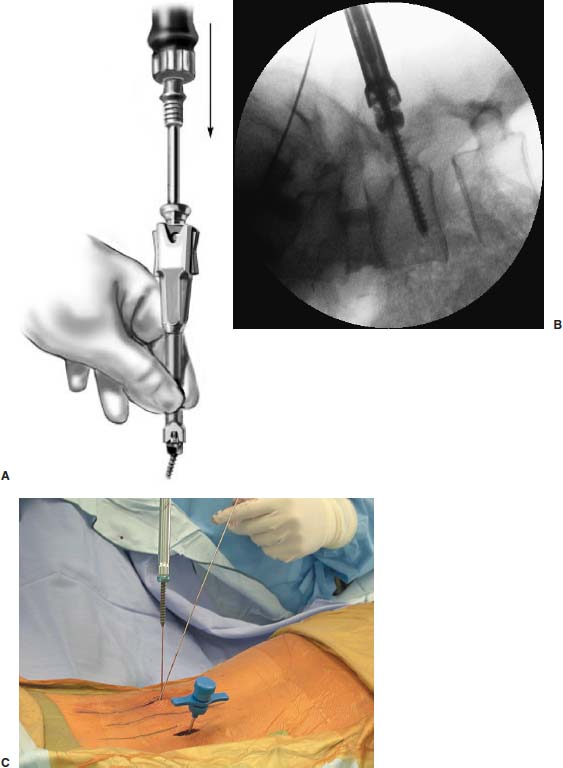
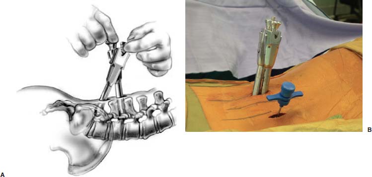
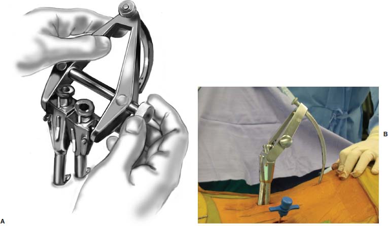
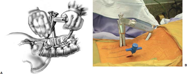
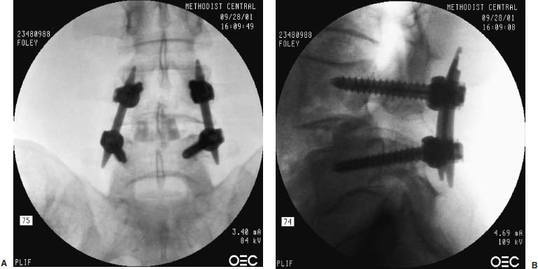
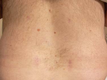
Pedicle screw fixation has become a widely accepted method for spinal stabilization. This technique provides rigid, three-column stability and can be used in the surgical management of a wide range of spinal disorders. One of the disadvantages of traditional pedicle screw placement, however, is that it requires extensive soft tissue dissection to expose the anatomical landmarks and achieve the proper trajectory for screw insertion. The tissue trauma that occurs during the surgical exposure can be considerable and is at least partially responsible for the significant cost and lengthy hospital stays associated with instrumented lumbar fusion.1 In addition, the morbidity associated with these procedures has become an increasing concern for many surgeons. In part, this morbidity is related to the significant iatrogenic muscle and soft tissue injury that occurs during routine lumbar fusion exposures. Multiple authors have documented the harmful effects of the extensive muscle dissection and retraction that normally occur during lumbar procedures.2–8 Kawaguchi et al2,3 analyzed the effects of retractor blade pressure on the paraspinous muscles during lumbar surgery. They determined that elevated serum levels of creatine phosphokinase MM isoenzyme, an indicator of muscle injury, is directly related to the retraction pressure and duration. These findings support the work by Gejo et al,4 who examined postoperative MRIs and trunk muscle strength in 80 patients who previously had lumbar surgery. They concluded that the damage to the lumbar musculature was directly related to the time of retraction during surgery. Furthermore, the incidence of low back pain was significantly increased in patients who had long muscle retraction times. Styf and Willen5 determined that retractor blades may actually increase intramuscular pressure to levels of ischemia. Mayer et al6 evaluated trunk muscle strength in patients who had previous lumbar surgery and found that patients who had undergone fusion procedures were significantly weaker than those who had undergone diskectomy. Rantanen et al7 concluded that patients with poor outcomes after lumbar surgery were more likely too have persistent pathologic changes in their paraspinal muscles. In this chapter we will describe a technique and instrumentation designed by the senior author (KTF) for minimally invasive posterior fixation of the lumbar spine by using percutaneous screws and rods (Sextant; Medtronic Sofamor Danek, Memphis, TN). Paraspinous tissue trauma is greatly minimized without sacrificing the quality of the spinal fixation. Although percutaneous lumbar pedicle screw insertion has previously been reported, a minimally invasive approach to inserting a longitudinal connector for these screws has proven more challenging. The Sextant system allows for the straightforward placement of lumbar pedicle screws and rods through percutaneous stab wounds. The screws and rods are placed in an anatomical position similar to that achieved by an analogous open surgical approach. Minimally Invasive Lumbar Interbody Fusion A tubular retractor system was first developed for microdiskectomy in 1994 by Foley and Smith9; its basic concept is the foundation on which several contemporary approaches to minimally invasive posterior lumbar fusion are based. The system consists of a series of concentric dilators and thin-walled tubular retractors of variable length. The spine is accessed via serial dilation of the natural cleavage plane between muscle fascicles, instead of a more traumatic muscle-stripping approach. The use of a tubular retractor, rather than blades, allows the retractor itself to be thin-walled (0.9 mm), even when the wound is quite deep. In addition, unlike blades, the tube circumferentially defines a surgical corridor through the paraspinous tissues. This helps prevent muscle from intruding into the exposure. All of the midline supporting musculoligamentous structures are left intact with this technique. An appropriately sized working channel is created that permits spinal decompression and fusion. Surgery can be performed using the operating microscope, loupes, an endoscope, or a combination of techniques, depending on the preference of the surgeon. The tubular retractor approach can be utilized for minimally invasive lumbar fusion via posterolateral onlay posterolateral interbody fusion (PLIF) or transforaminal lumbar interbody fusion (TLIF). Sextant Percutaneous Pedicle Screw and Rod Fixation This section will describe the technique for Sextant percutaneous pedicle screw and rod fixation. Of course, the percutaneous instrumentation is always performed in conjunction with fusion. The fusion may be done anteriorly (standard, mini-open, or laparoscopic anterior lumbar interbody fusion, ALIF). If so, then the patient is merely turned to the prone position after the ALIF (same operative setting), and the percutaneous screws and rods are inserted. Each screw is placed through a 14 to 15 mm incision. Because of the lumbar lordosis, the small incisions for screw placement at L5–S1 typically overlap; thus, both screws are placed through the same 1-inch (2.56 cm) incision. If the patient requires a concomitant posterior decompression, or if there is no indication (or a contraindication) for an ALIF, posterior and posterolateral approaches to fusion are performed in conjunction with Sextant fixation. We typically perform these in minimally invasive fashion using a 22 mm diameter tubular retractor. This tubular retractor, which derives from the microendoscopic diskectomy technique, can be inserted through a 1-inch (2.56 cm) paramedian incision and relies on the same muscle-splitting principle that is used with the Sextant system. We have used this approach for instrumented PLIF and TLIF. Once the fusion has been performed through the tubular retractor, the retractor is removed, and the Sextant instrumentation is inserted through the same 1-inch (2.56 cm) incision. Single-level posterior and posterolateral fusion and pedicle screw instrumentation can therefore be performed through bilateral, paramedian 1-inch (2.56 cm) incisions. Sextant fixation has also been successfully applied to two-level fusion and fixation. Patient Position PLIF Using the METRx and Tangent Technique FIGURE 23–1 PLIF using the METRx and Tangent system. FIGURE 23–2 Placement of the Tangent interbody bone graft as seen through a METRx tubular retractor system. Sextant Screw and Rod Placement Technique The Sextant screws are inserted through the same 1-inch (2.56 cm) incisions that were used for the tubular retractors. The pedicles are localized with anteroposterior and lateral fluoroscopy. The FluoroNav Virtual Fluoroscopy System (Medtronic Sofamor Danek) can be utilized as an alternative. FIGURE 23–3 (A) Bone biopsy needle is used to gain access to the pedicle. (B) Pedicle entry. Anteroposterior fluoroscopy should show the tip to be located at the lateral margin of the pedicle cylinder. (C) As the needle reaches the pedicle-vertebral body junction, the tip should be positioned in the center of the pedicle on the anteroposterior image. FIGURE 23–4 Once the needle has safely entered the vertebral body, the inner trocar is removed, and the K-wire is placed into the needle. A power driver is used to pass the wire through the pedicle under serial AP and lateral fluoroscopic guidance. (A) Artist depiction of a K-wire through the trocar. (B) Lateral x-ray. (C) Intraoperative picture. FIGURE 23–5 After the K-wire has been positioned, the sequential dilators are placed. (A) Artist depiction. (B) Lateral x-ray. (C) Intraoperative picture. FIGURE 23–6 The pedicle is tapped with the cannulated tap. (A) Artist’s depiction. (B) Lateral x-ray. (C) Intraoperative picture. FIGURE 23–7 Screw extender assembly. (A) Inner screw driver placed within screw extender shaft. (B) Engagement of the locking screw and screwdriver on the polyaxial screw head. FIGURE 23–8 The entire screw-extender assembly is placed over the K-wire, and the screw is inserted into the pedicle under fluoroscopic guidance. (A) Artist’s depiction. (B) Lateral x-ray. (C) Intraoperative picture. Results Sixty-three patients have undergone percutaneous pedicle screw and rod insertion with the Sextant system at our institution since March 2000. Thirty-nine of the patients have been followed for at least 12 months. Twenty-two of the patients were male, and 17 were female. Their ages ranged from 23 to 80 years, with a mean of 46 years. The diagnoses were isthmic spondylolisthesis in 17 patients (11 grade I, 5 grade II, and 1 grade III), degenerative spondylolisthesis (stenosis) in 15 patients, degenerative disk disease in five patients, and one trauma; the remaining two patients suffered from symptomatic nonunion related to previous failed fusion. Thirty-seven patients had single-level fusions, and two had two-level fusions. Twenty-five patients underwent concomitant ALIF, 12 underwent minimally invasive PLIF or TLIF, one underwent a minimally invasive retroperitoneal approach, and one had a minimally invasive posterolateral fusion. The instrumented levels were L5–S1 in 19 patients, L4–L5 in 16 patients, L3–L4 in one patient, and L2–L3 in one patient. Two patients underwent twolevel fusion and fixation (one L3–L5 and another L4–S1). FIGURE 23–9 The maneuver of aligning the extender surfaces external to the patient also aligns the screw saddles beneath the paraspinous muscle, readying them for rod insertion. (A) Artist’s depiction. (B) Intraoperative picture. FIGURE 23–10 Once the surfaces are flush against one another, the rod inserter is connected to the two screw-extender assemblies. (A) Artist’s depiction. (B) Intraoperative picture. FIGURE 23–11 The rod connects to the screw-extender-inserter assembly in such a fashion that the rod is geometrically constrained to pass along an arc that intersects the openings in the screw saddles. (A) Artist’s depiction. (B) Intraoperative picture. FIGURE 23–12 Postoperative anteroposterior (A) and lateral (B) x-rays after a METRx-Tangent-Sextant percutaneous PLIF. FIGURE 23–13 Postoperative scar as seen in clinic. The mean length of follow-up was 22 months, with a range of 12 to 38 months. All patients but one improved clinically (26 excellent, 12 good by MacNab criteria); one patient who presented with mechanical low-back pain had persistent mechanical low-back pain despite a solid fusion. One patient required replacement of a loose lock plug 1 month postoperatively. The patient did well clinically, and the event was asymptomatic. Reoperation to replace the lock plug was performed on an outpatient basis. This event occurred early in our clinical experience and led to a redesign of the lock plug. No other device-related problems have been experienced. Solid fusions were obtained in all patients (contiguous bony bridging, no motion on flexion-extension views), and all rods and screws were placed in a satisfactory position. Percutaneous lumbar fixation was designed, in part, to minimize the paravertebral muscle injury that occurs with conventional open procedures. Magerl10 first reported the use of percutaneous pedicle screws combined with an external fixator in 1982. The most obvious limitation of this technique was the risk of infection, not to mention the discomfort of an external appliance. Mathews and Long11 described the use of percutaneous pedicle screws with longitudinal connectors placed under direct vision in the suprafascial, subcutaneous space. This superficial instrumentation was uncomfortable to the patient and associated with a significant nonunion rate as well, perhaps secondary to the long lever arms of the hardware. The Sextant system allows for placement of percutaneous screws and rods through paramedian stab incisions. The conventional anatomical position of the construct avoids the instrumentation-related discomfort that was associated with earlier versions of percutaneous fusion. The geometrically constrained arc produced by the Sextant apparatus simplifies the connection of the percutaneous rods and screws. There are several distinct advantages of the Sextant system compared with standard open lumbar pedicle fixation. The paraspinous muscles are bluntly separated rather than stripped from their attachments and are minimally retracted using a sequential dilation technique, as described by Foley and Smith9 for microendoscopic diskectomy. This results in significantly less intraoperative blood loss, less iatrogenic muscle injury, and less postoperative pain. Patients are therefore able to ambulate and mobilize much more quickly, resulting in a decreased rate of perioperative complications, shorter hospital stays, and decreased cost.12 From a technical perspective, it is also easier to achieve the desired lateral to medial pedicle screw trajectory because there is not a wall of soft tissue that limits the angulation of the instruments (as can be encountered in the open surgery). This is particularly helpful in obese patients because more extensive exposure and retraction can be avoided. Operative time is also significantly lessened; it takes only 1 hour for the surgeon to place four screws and two rods. The Sextant system is an emerging component in the rapidly developing field of minimally invasive spine surgery. It is an important advancement and serves as a complement to other newly established minimally invasive fusion techniques for ALIF, PLIF, TLIF, and posterolateral onlay fusion. As the technology continues to evolve, the indications for Sextant will certainly expand from primarily degenerative disease to include multilevel fusions for spinal disorders due to trauma and neoplastic conditions. The clinical utility of Sextant appears promising because our early experience suggests that the system is able to achieve the same clinical results as conventional open procedures while significantly reducing the exposure-related morbidity. REFERENCES 4. Gejo R, Matsui H, Kawaguchi Y, et al. Serial changes in trunk muscle performance after posterior lumbar surgery. Spine. 1999;24: 1023–1028. 9. Foley KT, Smith MM. Microendoscopic discectomy. Tech Neurosurg 1997;3:301–307.
23

Endoscopic/Percutaneous Lumbar Pedicle Screw Fixation

< div class='tao-gold-member'>
Endoscopic/Percutaneous Lumbar Pedicle Screw Fixation
Only gold members can continue reading. Log In or Register to continue

Full access? Get Clinical Tree


