Fig. 11.1
A 55-year-old with back and radicular pain due to grade II spondylolisthesis at L5/S1. Tubular retractor in place. The decompression has been performed through a 22 mm tubular retractor and the disc space is being entered
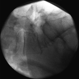
Fig. 11.2
An expandable interbody cage has been applied. The tubular retractor has been removed and the screws will be placed next
Next, the navigation reference array (VectorVision®, Brainlab AG, Feldkirchen, Germany) is attached with 2 percutaneous Steinman pins to the posterior iliac crest. A 3-D image set is obtained using the Siremobil Iso-C3-D (Siemens AG, Munich, Germany) and imported into the navigation system. Using a navigated pointer or drill guide through a mini-open or percutaneous approach, the ideal trans-pedicular trajectory is determined, and the diameter and length of the planned screws are simulated on the screen (Fig. 11.3). We currently use a custom-made navigated drill tube that allows the insertion of a drill, tap, and a pedicle screw without screwhead [10]. The advantage of this system is that it avoids the use of K-wires and that it reduces the number of instruments that need to be navigated (Figs. 11.4 and 11.5).
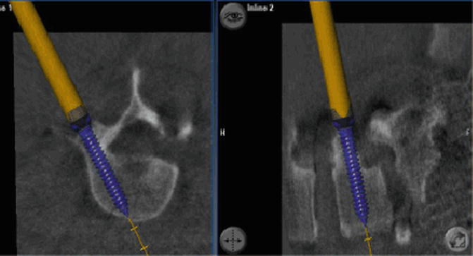
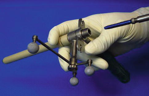
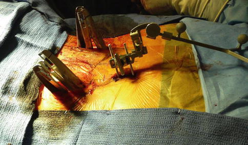

Fig. 11.3
Using a navigated pointer or drill guide through a mini-open or percutaneous approach, the ideal trans-pedicular trajectory is determined, and the diameter and length of the planned screws are simulated on the computer screen

Fig. 11.4
Navigated drill tube that allows the insertion of a drill, a tap, and a pedicle screw without screwhead. The advantage of this system is that it avoids the use of K-wires and that it reduces the number of instruments that need to be navigated

Fig. 11.5
The screw extension posts are visible through two small incisions. Steinman pins with reference array have been placed into the left iliac crest. The rods will be measured and placed next
Several other options are available: A navigated drill guide can be used that allows the preparation of a starting hole with various sized drill bits into the pedicle. K-wires can then be introduced over which the tap and screws can be inserted. The advantage of this approach is that a control spin can be obtained with the K-wires in place to confirm accurate positioning. A third option involves the use of precalibrated instruments including the awl, pedicle probe, tap, and screwdriver. Many spinal instrumentation manufacturers have these now available. Nottmeier recently described how this approach can be utilized in order to implant pedicle screws without the use of K-wires [11].
Navigation can also be used to determine the ideal positioning and trajectory of the TLIF or PLIF cage and in order to determine the desired rod length by measuring the distance between the screwheads (Figs. 11.6 and 11.7).
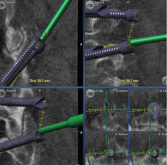
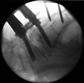

Fig. 11.6
Navigation can be used to determine the desired rod length by measuring the distance between the screwheads

Fig. 11.7
Steinman pins with reference array have been placed into the iliac crest. Screws have been placed with a navigated drill guide. Rods have been locked in place
11.6 Complex and Deformity Surgery
Stereotactic navigation is especially useful in patients with more complex anatomy, such as significant spondylolisthesis or degenerative scoliosis. Navigation can also be used to determine the best trajectory for intervertebral cage placement and for trans-sacral fixation [12] (Fig. 11.8). In the lumbar spine, it is used to determine the length of rods and to align screws during a multilevel fusion so that the percutaneous rod placement is facilitated. In the cervical spine, CAS facilitates the minimally invasive resection of odontoid masses via a transnasal route, which is a significant improvement when compared to conventional maximally invasive transoral surgery [13, 14].
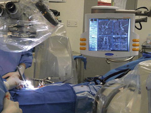

Fig. 11.8
The use of 3D navigation under the microscope to determine the optimal entry point and angle of an intervertebral cage
In more complex thoracolumbar deformity cases, the interbody part is frequently being accomplished via a separate anterior or lateral approach. This surgery may also include the placement of iliac crest screws [15]. In principle, navigation is performed in a similar fashion as described above (Fig. 11.9a, b).
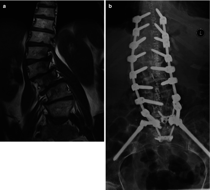

Fig. 11.9
A 75-year-old patient with back and leg pain before and after MIS deformity correction. (a) Preoperative MRI showing significant degenerative scoliosis. (b) Postoperative AP X-rays demonstrating placement of pedicle screws from T10 to L5 and iliac crest screws. Instrumentation was placed with 3D navigation
A few differences or additional challenges, however, apply. Some authors have reported good accuracy with multilevel cases where the reference array was placed > 10 levels away from the surgery site [8]. We disagree and recommend placement of the reference array into the iliac crest for cases up to L3. If the fusion extends above L3, we will typically reposition the reference array more cranially using a spinous process clamp. In our experience this will maximize accuracy and safety. Another challenge is that current intraoperative portable cone beam CT systems have a limited field of view and therefore only allow the imaging of up to 3–5 vertebral bodies. This adds time, radiation exposure, and complexity to multilevel deformity cases. The solution here is the use of a true intraoperative CT scanner.
The current advantage of using navigation in complex anatomy cases is that screw placement is clearly more accurate and technically more straightforward than with conventional AP/lateral fluoroscopy. Screw fit is maximized and there is no need to “skip” levels due to small or complex pedicle anatomy as is frequently seen in multilevel cases with conventional MIS techniques. A recent systematic literature review confirmed that navigation provided higher screw placement accuracy compared with conventional methods especially in scoliosis cases [16]. We found that CAS was associated with improved screw placement accuracy and that it was employed in cases with a higher degree of surgical complexity such as MIS cases, deformity, and revision surgery [17]. As the technology improves, it is likely that CAS will become more important in deformity surgery.
11.7 Navigation Without K-Wires
The use of K-wires can be harmful to the patient as they can break or bend during the procedure and cause visceral or vascular injury. In addition, the surgical workflow using K-wires is complex and requires the use of multiple instruments that go back and forth between the surgeon and the scrub nurse. We introduced a navigated guide tube that allows drilling, tapping, and the placement of the final screw without the need for K-wires [10]. This instrument facilitates the workflow in the operating room by reducing the number of instruments that need to be navigated and reduces the potential risks associated with current techniques for the insertion of percutaneous or mini-open pedicle screws by eliminating the need for K-wires (Fig. 11.4). Nottmeier recently described an approach to implant pedicle screws without the use of K-wires using precalibrated instruments including an awl, pedicle probe, tap, and screwdriver [15].
11.8 Radiation Exposure
When used intelligently, CAS can help make spine surgery safer for the patient as well as the surgeon and the operating room staff: The issue of radiation exposure using 2nd-generation CAS for MIS has been addressed by Nottmeier et al. [18]. In 25 MISS cases with 228 screws placed using a portable cone beam CT navigation, there was no radiation exposure to the surgeon. This requires, though, that K-wires are not used.
11.9 Learning Curve and Troubleshooting
Navigation does not replace surgical experience, judgment, meticulous preparation, and technique. For the surgeon who uses navigation for the first time, it will neither make surgery “easier” nor will it facilitate the workflow. Navigation requires careful planning and training not only for the surgeon but also for the whole team: the scrub nurse, the assistants, the X-ray technician, and others. There is a learning curve and initially some additional time will be required to successfully incorporate navigation. Many of the initial negative reports on navigation were due to the first generation systems not being user-friendly and that surgeons did not spend the time to really master this new technique. In the author’s experience, one of the hardest tasks is to teach navigation to assistant surgeons who do not have the experience and understanding and who may believe that navigation enables “videogame” or “plug and play” surgery. The contrary is true: Accurate navigation requires very meticulous and gentle surgical technique and constant vigilant interpretation of what the computer screen shows versus the surgeon’s tactile feedback. Subtle discrepancies may indicate a mismatch between the actual anatomy and what the screen shows and this requires immediate troubleshooting. In the majority of cases, this does not mean that navigation failed. Easily correctable reasons include:
The surgeon’s instrument may exert too much pressure that can lead to distortion of the anatomy. For this reason, we prefer using a battery-driven drill rather than a navigated awl or pedicle finder.
Contamination of the reflective beads with blood.
Loosening of the reference array on one of the instruments due to mechanical irritation or the use of a mallet to impact the instrument.
“Skiving” of the navigated instrument off the bone, especially along the lateral facet joint. For this reason it is helpful to try and place the entry point of the instrument over a flat bone surface. The use of a battery-driven drill also minimizes slipping off the bone.
Stay updated, free articles. Join our Telegram channel

Full access? Get Clinical Tree


