Fig. 29.1
Patient positioning for left lateral MIS approach to the thoracolumbar spine. Arms are abducted, and torso is fixed by supportive pads at the shoulders, sternum, sacrum, and symphysis to assure adequate anatomical orientation by maintaining exact lateral position. Access to the thoracolumbar spine must be kept clear circumferentially, especially if simultaneous posterior instrumentation is intended. The iliac crest is commonly used as fixation point for the image-guidance dynamic reference frame and should therefore also be draped and be accessible during surgery
The rib directly overlying the lesion and the outlines of the affected and adjacent vertebral bodies are marked on the skin under fluoroscopy – schematic line drawing). The length of the skin incision depends on the intended procedure. For monosegmental spondylectomy and VBR, a 5–6 cm incision is adequate. Incisional length is extended to 8 cm for bilevel pathology or 10–12 cm for multiple segments – schematic line drawing). Sufficient mobilization of the skin and subcutaneous areolar tissue from the outer chest cage is important to permit soft tissue retraction craniocaudally and ventrodorsally during dissection and instrumentation. This will also allow for lateral instrumentation to be placed through additional thoracoports inserted one or two intercostal spaces above/below the rib resection site – schematic line drawing). An 8 cm rib segment is dissected subperiosteally and removed. The intercostal neurovascular bundle is mobilized off the costal sulcus, covered with a moist sponge and deflected into the chest cavity to avoid retraction-related intercostal neuralgia. Introducing the frame-retractor blades, the parietal pleural is then mobilized from the chest wall using blunt finger dissection or a peanut sponge – schematic line drawing). Mobilization of the parietal pleura is initialized around the rib removal site (i.e., ventrally and near the supra- and infrajacent ribs) before redirecting the retropleural dissection towards the spine. This will minimize the likelihood of pleural tears. The valves of a table-fixed frame retractor [30] are frequently adjusted during this process, facilitating retropleural dissection by keeping the interface between parietal pleura and chest wall under constant tension. The sympathetic chain, segmental vessels, thoracic duct (left-sided approach), and the azygous/hemiazygous veins are contained against the vertebral bodies within this areolar tissue layer [22, 32, 52] – schematic line drawing). Once the rib heads are visualized, an attempt can be made to mobilize the sympathetic chain off the spinal surface along with the pleura. Unlike the thoracic duct and veins, the sympathetic chain may be difficult to preserve and can be divided at the approach level without sequelae. Segmental vessels are isolated, ligated, and divided as dictated by pathology and surgical goal. If the ALL needs to be released during kyphosis correction, the dissection is carried between anterior vertebral surface and vessels to the contralateral side – schematic line drawing). Once the vessels are protected by a wide spatula, the ALL can be divided. Removal of the pedicles at the level of pathology allows for early identification of the spinal canal – schematic line drawing). To address lesions at the thoracolumbar junction, the retropleural and retroperitoneal spaces may need to be connected to gain full access to the spine/spinal canal and to place the instrumentation. The retroperitoneal space is entered by dividing the costal cartilage of the 11th or 12th ribs [22, 32, 37, 52] and the psoas muscle is bluntly split en route to the spine [4, 6, 17, 24, 45, 48, 54]. The extent of associated rib removal depends on both individual anatomy and required surgical access dimensions. In contradistinction to the original descriptions of thoracolumbophrenic access [37, 38], extensive division of the diaphragm itself is not required. Only the most proximal diaphragmatic insertions on the thoracolumbar spine (L1, L2) are dissected off the lateral spinal surface to connect the retropleural and retroperitoneal spaces [11, 17, 45, 55] – schematic line drawing). Overlying skin, soft tissues, pleura, diaphragm, and peritoneal sac are retracted by multiple valves of a table-fixed retractor to allow for simultaneous visualization of supra- and infradiaphragmatic extensions of the combined approach. Closed chest tube drainage usually is not required. If a visceral pleural leak (i.e., air fistula) or a parietal pleural tear should occur that cannot be addressed by direct suture or application of a sealant (e.g., a fibrin-coated collagen sponge), a small chest tube is placed directly through from the approach site. Otherwise, a single large vacuum drain (12Ch) is left in the retropleural space to promote reattachment of the parietal pleura to the chest wall for 3–4 days. Mid-thoracic (true) ribs are approximated and secured with nonabsorbable sutures. The wound is closed anatomically in layers, with the skin either sutured or sealed with cyanoacrylate. Postoperative chest X-rays to exclude clinically relevant pneumo-/hemothorax are obligatory before discharge of the patient from the ICU.
29.7 Extracoelomic Approach to the Thoracolumbar Junction
The thoracolumbar junction may be accessed either via a primarily transthoracic retropleural route [1, 2, 13, 14, 30, 34, 42, 43, 57] (working downward with transdiaphragmatic extension into the retroperitoneal space at L1 or L2) or via a retroperitoneal approach working upward through the insertion of the medial diaphragm arcade [11] with subsequent retropleural dissection along the lateral spine surface [3, 17, 45, 54]. The choice of the most suitable approach is dictated by individual chest cage anatomy (position, angulation, and length of the 10th to 12th ribs), the intended instrumentation, and surgeon preference.
29.8 MIS Thoracic Interbody Surgery via Posterolateral Extracavitary Approach
Our preferred MIS variant of the posterolateral extracavitary approach (PECA) involves partial removal of the proximal 8–10 cm of the rib at the level of the pathology with the patient in regular prone position (Fig. 29.2). The approach side needs to be ipsilateral to the location or major extension of pathology, respectively, since the PECA does not offer a lateral working trajectory tangential to the spinal canal – schematic line drawing). This feature of PECA precludes the treatment of lesions that require radical VBR, comprehensive anterior column manipulation, division of the ALL, or full pedicle-to-pedicle visualization of the spinal canal. However, posterior pedicle screw fixation can easily be performed without repositioning the patient. Therefore, in our hands this approach is a preferred option in the treatment of spinal metastasis, rather than deformity. Like in retropleural thoracotomy, blunt dissection of the parietal pleura commences at the site of rib removal. This retropleural plane is progressively developed to expose the rib head(s) and then the lateral vertebral body wall, up to its anterior border – schematic line drawing). For VBR, at least one spinal nerve root needs to be divided to gain enough space for insertion of the distraction cage. In contradistinction to the lateral retropleural approach, the trajectory during VBR cage insertion is invariably oblique. For lordotic anterior column reconstruction, instrumentation systems allowing for insertion of lordotic VBR devices from variable oblique angles (e.g., Obelisk®, Ulrich Medical, Ulm, Germany) [45, 54] are recommended.
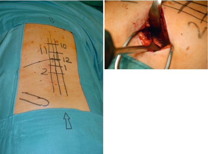
Fig. 29.2
MIS lateral extracavitary approach to Th12. Left image – overview showing skin markings of midline, pedicle rows, and positions of Th10–L2 pedicles. Lower left mark indicates posterior iliac crest. Right image – operative situs following resection of proximal left 12th rib and retropleural dissection to the costovertebral joint. Cobb elevator is placed below rib head. The dissection remains entirely lateral to and therefore spares the erector trunci muscle
29.9 MIS Corpectomy and Vertebral Body Replacement
Removal of adjacent discs greatly facilitates anatomical orientation during subsequent corpectomy. Discectomy and/or corpectomy is performed using long-handled instruments (chisels, elevators, rongeurs, curettes, or a power burr). If spinal canal decompression is required, the posterior vertebral wall is initially left intact during corpectomy, then progressively thinned down, and finally displaced ventrally into the corpectomy defect with a long slim Cobb dissector, directing it away from the thecal sac – schematic line drawing). Adequacy of decompression may be assessed by either passing a blunt nerve hook along the posterior vertebral surface and below the thecal sac to the contralateral side, epidural contrast medium instillation with subsequent fluoroscopy (intraoperative epidurography), or intraoperative 3D imaging (isocentric C-arm or intraoperative CT technology).
A variety of interbody devices may be used for anterior column reconstruction [1, 15, 29, 33, 40, 45, 47, 53, 54]. Implants of specific interest for deformity surgery are (a) hyperlordotic intervertebral cages (lordosis angle 16°–25°) and distractable VBR cages with variable angle end plates. The individual choice of implant depends on correction requirements, the size of gap that needs to be closed, the number of segments addressed, and availability of instrumentation suitable for MIS. We use individually trimmed titanium mesh cylinders as hyperlordotic intervertebral cage to close PSO gaps. For VBR, our preferred implant is a hollow cylindrical titanium distractable device equipped with variable angle end plates (Fig. 29.3) that is manufactured in various sizes to bridge corpectomy voids of up to three segments (Obelisk®, Ulrich Medical, Ulm, Germany) [45, 54]. In the elderly and in patients with questionable or proven poor bone quality, we routinely reinforce the vertebral bodies flanking distractable VBR devices with PMMA (i.e., intraoperative vertebroplasty) to prevent subsidence and vertebral stress fracture (Fig. 29.4).
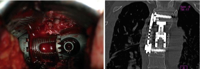
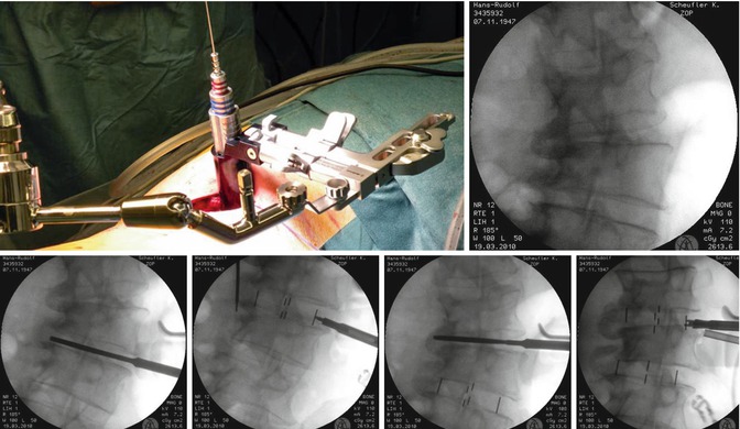
Fig. 29.3
MIS bisegmental (Th4 and Th5) vertebral body replacement (VBR) via right-sided retropleural approach. The aortic arch is overlying the left lateral vertebral surface in the upper thoracic spine. Left image – the parietal pleura is held below two retractor blades (upper image border); the spinal canal is oriented parallel to lower image border. VBR device is fully expanded, and the locking nut is engaged. Right image – corresponding postoperative coronal CT reconstruction, demonstrating VBR device and lateral plate
Fig. 29.4
MIS correction of thoracolumbar scoliosis (degenerative adult scoliosis) in a 62-year-old male via left-sided DLIF. Upper left image – intraoperative situs after insertion of the tubular retractor. Upper right image – initial intraoperative A-P radiograph before correction. Note solid lateral syndesmophytes on concave right side, requiring aggressive intersomatic release during correction. Lower row – intraoperative radiographs during sequential intersomatic release and insertion of intervertebral cages. Note the frontal correction release following release of syndesmophytes on final image
29.10 MIS Deformity Correction
MIS correction of thoracic hyperkyphosis or scoliosis by interbody techniques involves either multiple thoracic discectomies (Fig. 29.4) or columnotomy (oligosegmental corpectomy) with subsequent (hyper)lordotic intervertebral cage or VBR device insertion (Fig. 29.5). The thoracic and combined thoracoabdominal retropleural/retroperitoneal approaches provide suitable access for such procedures, specifically by granting visualization and control of prevertebral vessels and thecal sac during release and subsequent instrumentation. Spinal deformity correction maneuvers as well as VBR implant size and shape may be planned individually with the aid of specifically designed software, allowing for assessment of correction results and required hardware ahead of the actual intervention. The importance of meticulous surgical planning for successful completion of a complex MIS deformity procedure cannot be overstated. Comprehensive spinal fixation and deformity reduction usually involve either posterior pedicle-based fixation or anterolateral screw-rod fixation (Fig. 29.4). Posterior instrumentation may either be placed prior to or during the anterior procedure [25, 54]. Surgical options include insertion of provisional rods, which are replaced by definitive rods during anterior correction, and image-guided single-step circumferential instrumentation in the lateral decubitus position. Various surgical sequence strategies are currently evolving, as are specific implants, correction tools, as well as integration of surgical image-guidance and planning software.
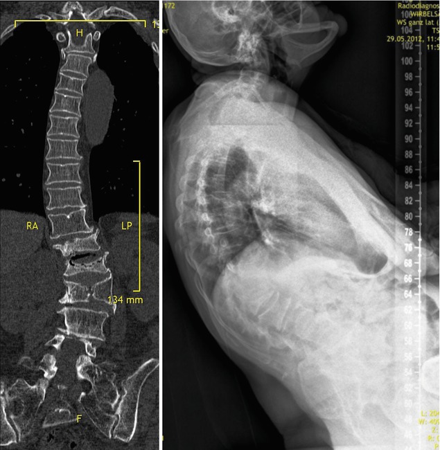
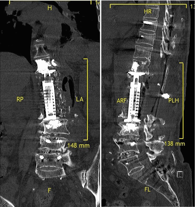
Fig. 29.5
MIS correction of thoracolumbar kyphoscoliosis (degenerative adult scoliosis) in a 67-year-old female via left-sided mini-open combined thoracolumbar extracoelomic approach. Upper left image – coronal CT reconstruction demonstrating fracture and lateral rotational displacement of the Th12, L1, and L2 vertebrae. Upper right image – full spine standing X-ray showing severe thoracolumbar kyphosis with marked compensatory pelvic retroversion. The patient was unable to walk for pain and sagittal imbalance. Lower left image – postoperative coronal CT reconstruction after deformity correction by trisegmental corpectomy/VBR (Th12–L2), DLIF L3/L4, and L4/L5 and complementary posterior fixation from T8 to sacropelvis. Note PMMA reinforcement of vertebra flanking the VBR device and placement of morcellized rib autograft lateral to the VBR device to promote fusion. Lower right image – postoperative sagittal CT reconstruction showing correction of sagittal profile, decompression of the spinal canal
29.11 Complications Avoidance and Management
The complication profile of MIS deformity procedures generally resembles that of conventional open procedures. Complications specifically related to MIS may arise from inability of the surgeon to accomplish the surgical goal(s) within the confines of an MIS exposure. In our experience, true MIS-related problems are rare and mostly due to inadequate surgical planning or experience. Few events may warrant conversion to a “standard” size approach:
Uncontrollable bleeding from laceration of a large vessel in the depth of the operative fieldRelated posts:
 Costs of Minimally Invasive Spine Surgery
 Sagittal Balance
 Lumbopelvic Parameters
 Presacral Approach for Discectomy and Interbody Fusion in the Setting of Minimally Invasive Spine Surgery Deformity Correction
 Minimally Invasive Thoracolumbar Facet Joint Fusion
 Minimally Invasive Wiltse Approaches for Posterolateral Fusion

Stay updated, free articles. Join our Telegram channel

Full access? Get Clinical Tree


