Chapter 124 Percutaneous Stereotactic Rhizotomy in the Treatment of Intractable Facial Pain
In this chapter, we review the most relevant data and classic papers1–8 associated with the various physiologic and ablative procedures. Using the experiences of our patients and evidence in the literature, we conclude that the percutaneous techniques, best represented by radiofrequency rhizotomy, provide the most effective and reproducible results, enduring long-term relief from pain, and the fewest side effects when compared with other ablative procedures. Considering these findings and the ongoing refinements in treatment protocols, we now focus our efforts on training in the art and science of these technical procedures, especially for young neurosurgeons and others who treat facial pain. Dedicated to this training effort, our treatment paradigm, with its full complement of modalities, is carefully highlighted in this chapter, and in courses at annual meetings of the American Association of Neurological Surgeons, other educational efforts, websites of professional organizations, and patient support groups (e.g., Trigeminal Neuralgia Association).
Indications and Patient Selection
On the basis of our experience and a review of the literature, we conclude the following. First, percutaneous techniques and posterior fossa exploration offer advantages and disadvantages. Second, radiofrequency rhizotomy is the procedure of choice when medications fail and a first surgical treatment is considered to be unsafe. Age is not a reason in itself for rejecting the idea of a craniotomy as an effective treatment because many patients 75 years and older tolerate this procedure extremely well. Third, microvascular decompression of cranial nerve V is recommended for healthy patients, those with isolated pain in the first ophthalmic trigeminal division or in all three trigeminal divisions, and patients who desire no sensory deficit.9
Cannulization, Stimulation, and Lesion Production
Using the senior author’s experience in performing more than 4000 percutaneous stereotactic radiofrequency rhizotomies, we describe the three key steps of the procedure as (1) cannulization of the foramen ovale and the trigeminal cistern, (2) stimulation for pain reproduction and determination of intensity threshold, and (3) generation of an effective partial sensory lesion. To this end, we first review the nuances related to the successful cannulization of the foramen ovale and trigeminal cistern. Secondly, we define the subtleties of stimulation that allow for superior lesion production. Finally, we provide an algorithm that allows for the generation of an effective partial sensory lesion. This three-step approach to percutaneous radiofrequency rhizotomy of the trigeminal nerve has proven safe and effective in more than 95% of patients.
Step 1: Cannulation of the Foramen Ovale
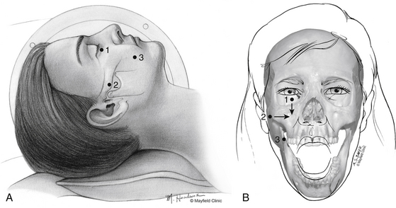
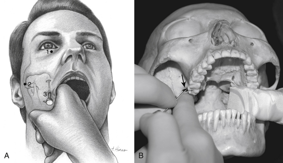
One hour before the procedure, 0.4 mg of atropine is administered intramuscularly to reduce oral secretions and prevent bradycardia. The patient is positioned supine on the fluoroscopic table with the head neutral. Next, Hartel’s three anatomic landmarks are plotted on the face: a point beneath the medial aspect of the pupil, a point 3 cm anterior to the external auditory meatus, and a point 2.5 cm lateral to the oral commissure (Fig. 124-1A and B).10 The first two points provide the rostral/caudal and medial/lateral trajectories for the penetration of the foramen ovale, and the third point is where the needle penetrates the skin of the jaw. The affected cheek is prepared with Betadine (Purdue-Frederick, Norwalk, CT). A 21-gauge spinal needle placed in the deltoid subcutaneous tissue acts as a reference and grounding electrode, or alternatively, a bovie pad can be used.
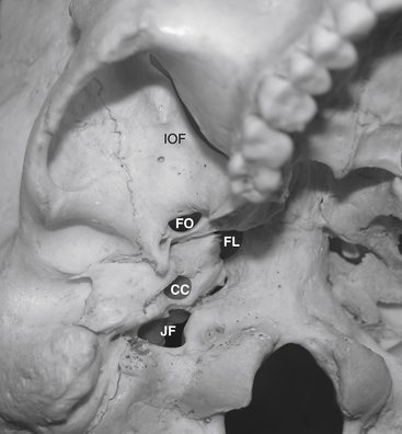
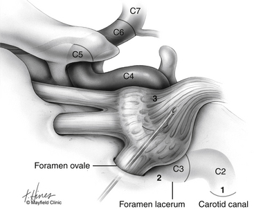
Before cannulization of the foramen, understanding the skull base anatomy and its anatomic variants is essential (Fig. 124-2). Aberrant placement of the cannula can result in unintended neurovascular injuries. Use of lateral fluoroscopic imaging will aid in avoiding the following: cannulization of the inferior orbital fissure (IOF) anterosuperiorly or the jugular foramen posteroinferiorly, or intracranial placement of the cannula through aberrant foramina (e.g., foramen of Vesalius, which lies anteromedial to the foramen ovale, or innominate canal of Arnold, which lies posterior to the foramen ovale). Pulsatile blood flow through the cannula indicates penetration of the internal carotid artery (ICA). Puncture of the ICA can occur in three locations: at the proximal C2 segment at the carotid canal, the C3 segment with the electrode passing through the cartilage of the foramen lacerum, and the cavernous (C4) segment (Fig. 124-3). This third type of penetration was described by Rish,11 who noted that an anteromedial electrode passing through the foramen ovale can penetrate the C4 segment of the ICA. If ICA penetration occurs, the cannula is withdrawn promptly, manual pressure is applied over the posterior pharyngeal space, the procedure is discontinued, and the patient is allowed 24 to 48 hours to convalesce. Ischemic complications, such as hemiparesis, and carotid-cavernous fistula have resulted from puncture of the ICA.11 Generally, arterial punctures are minimized by refraining from broad angular readjustments of the electrode and diligent attempts to avoid trajectories that are either posterolateral or posteromedial to the foramen of ovale; such trajectories jeopardize the carotid canal and foramen lacerum, respectively.
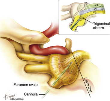
The primary goal of the cannulization step is penetration of the medial portion of the foramen ovale and placement of the electrode’s tip in the retrogasserian rootlets (Fig. 124-4). Using Hartel’s landmarks, we advocate either the direct penetration technique or the sequential palpation in which the surgeon sequentially walks the cannula down the smooth surface of the infratemporal fossa toward the superior-medial aspect of the foramen (Fig. 124-5). If the cannula enters the posterolateral aspect of the foramen, it may elude the trigeminal cistern and not contact the trigeminal ganglion within its dural investment. Additionally, as the electrode is advanced, it may not reach the maxillary or ophthalmic divisions of the rootlet.
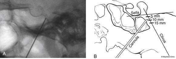
To begin, a 9-mm airway turned sideways or a bite block is inserted into the patient’s mouth between the molars on the opposite side to prevent the patient from involuntarily biting the surgeon’s finger. The patient is anesthetized with a rapid intravenous injection of 30 to 50 mg of methohexital (Brevital) followed by a 10-ml saline flush. Once the patient is fully asleep, the surgeon inserts the indexed finger of gloved hand inside the patient’s mouth, sliding along the inferior and medial wall of the lateral pterygoid to a point where it hooks around the lateral pterygoid, to guide the cannula toward the foramen ovale. A standard 100-mm, 20-gauge cannula, with its stylet in place, is inserted into the cheek 2.5 cm lateral to the oral commissure. The cannula is aimed toward the intersection of an axial plane, passing 3 cm anterior to the external auditory meatus, and a sagittal plane, passing through the medial aspect of the pupil. Although placement is by free-hand manipulation, fluoroscopic visualization is important to assist localization. Use of the image intensifier in the lateral plane effectively localizes the needle.4 Entrance of the cannula into the foramen ovale is signaled by a wince and a brief contraction of the masseter muscle, indicating contact with the mandibular sensory and motor fibers. Before the cannula is advanced any further, a lateral fluoroscopic image is obtained to confirm proper placement in the foramen ovale (Fig. 124-6). Fluoroscopy allows targeting a point along the lateral projection of the clivus, which is 5 to 10 mm below the floor of the sella. If difficulty penetrating the foramen ovale ensues, one should pause and return to a fundamental principle—namely, the safest approach to the foramen ovale is a trajectory that begins anteromedially to the foramen. In this manner, the surgeon can sequentially palpate, using the cannula along the smooth surface of the infratemporal fossa, and enter the superior medial aspect of the foramen. Use of this technique ensures a cannula trajectory in which the electrode will enter the trigeminal cistern at an angle and then sequentially contact each of the three divisions of the trigeminal root. Furthermore, targeting the anteromedial portion of the foramen ovale reduces the risks associated with probing alternative portions of the skull base, lowers the incidence of hematoma due to venous or arterial hemorrhage, and increases the probability of entering the trigeminal cistern.
Step 2: Stimulation of the Trigeminal Nerve
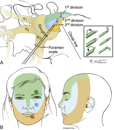
Targeted stimulation begins with the manipulation of the electrode’s tip in two dimensions as viewed on lateral fluoroscopy: the relationship of the electrode tip to the profile of the clivus and the curvature of the electrode’s tip. When the tip rests at the clival level, a stimulating pulse typically elicits paresthesias in the maxillary division rootlets. Advancement beyond the clival profile moves the electrode into the territory of the ophthalmic division rootlets, while withdrawal of the needle from the level of the clivus targets the mandibular division rootlets (Fig. 124-7A). The electrode’s tip should not be advanced more than 10 mm deep to the profile of the clivus because the tip can contact the trochlear or abducens nerve in this region. Sometimes the needle must be redirected more anteromedially to bring the tip closer to the posterior clinoid process for closer contact with the ophthalmic division. If the globe moves during stimulation, the cannula is too near the cranial nerves (CNs) in the cavernous sinus or perhaps near the brain stem. Stimulus-evoked facial contractions indicate that the electrode is either too deep, inclined too low on the clivus, or the stimulation level is too high. A lesion should not be made if there is any indication of motor nerve III, IV, VI, or VII stimulation or arterial bleeding.
After this initial placement and understanding of clival relationships, the axial rotation of the curved electrode permits a secondary form of targeting. Precise anatomic localization within the sensory root is aided by this maneuverability. The curved electrode tip is a coil spring that carries a thermocouple, stimulator, and lesion-generating probe. When the electrode is fully inserted into the cannula, the curved tip extends 5 mm beyond the end of the cannula and projects 3 mm perpendicular to the long axis of the electrode. Insulation of the cannula with polytetrafluoroethylene allows only the extruded portion of the electrode (0 to 5 mm) to be conductive. Rotation of the electrode can occur through a 360-degree axis for stimulation and lesion production (Fig. 124-7A). However, final placement of the electrode’s tip is determined by the patient’s response to electrical stimulation. In the sagittal plane, which can be viewed on lateral fluoroscopy, a tip projecting cephalad or medial provides better access to the fibers of the ophthalmic division, whereas the caudal or lateral projection should enable contact with the mandibular fibers. Additionally, if the electrode contacts the motor root and elicits stimulation of the masseter or pterygoid muscles, the electrode can be rotated laterally to reduce the incidence of a lesion that may result in a trigeminal motor paresis.
Alternatively, stimulation can be achieved with mild heat (less than 50 °C). The evoked response not only localizes but can reliably indicate the probe temperature required for lesion production. Consequently, the threshold current responsible for eliciting pain can be translated into a temperature and duration for the initial lesion, thus fulfilling the second objective. Our paradigm for conversion of a stimulus threshold voltage into a temperature and duration for an initial lesion is found in Table 124-1.
Table 124-1 Cincinnati Paradigm Used to Convert Threshold Stimulus into Lesion Temperature and Duration
| Stimulation Intensity (Volts) | Electrode Temperature (°C) | Duration of Lesion (Seconds) |
|---|---|---|
| <0.1 | 60 | 60 |
| 0.2–0.3 | 65 | 60 |
| 0.3–0.4 | 70 | 60 |
| 0.5–0.6 | 75 | 60 |
| 0.7–0.8 | 80 | 60 |
| >1.0 | No lesion; reposition electrode | |
Printed with permission from the Mayfield Clinic.
Stay updated, free articles. Join our Telegram channel

Full access? Get Clinical Tree


