Plain Film Radiography and Computed Tomography of the Cervical Spine: Part II. Classification and Subtypes of Spinal Injury
Alejandro Zuluaga Santamaria
Diego B. Nùñez Jr.
It is helpful to consider injuries to the cervical spine in terms of their mechanism (1). These mechanisms include flexion, flexion rotation, extension, extension rotation, vertical compression, lateral flexion, and imprecisely understood mechanisms that may result in odontoid fractures and atlanto-occipital dislocation. As emphasized by Harris (1), however, it is also important to note that different injuries may be caused by a single predominant force vector (2), and that there are groups of injuries that occur with each predominant force vector, with the magnitude of the force determining the extent of the injury. Cervical spine injuries can also be classified into upper and lower cervical injuries. Upper cervical injuries include injuries to the base of the skull
(including the occipital condyles or C0), C1, and C2. Lower cervical injuries (subaxial) include injuries from C3 through C7. A classification of cervical spine injuries are presented based upon the predominant force vector (Table 6-1), however they will be discussed and illustrated from the perspective of their location (upper and lower cervical spine) in the remainder of the chapter.
(including the occipital condyles or C0), C1, and C2. Lower cervical injuries (subaxial) include injuries from C3 through C7. A classification of cervical spine injuries are presented based upon the predominant force vector (Table 6-1), however they will be discussed and illustrated from the perspective of their location (upper and lower cervical spine) in the remainder of the chapter.
Stability versus Instability
Stable injuries resist movement in response to physiologic loading and do not create or worsen neurologic deficits. White and Punjabi (3) have defined “clinical instability” as “the loss of the ability of the spine under physiologic loads to maintain its pattern of displacement so that there is no initial or additional neurologic deficit, no major deformity, and no incapacitating pain.” The three-column concept of Denis (4) is very important in understanding the concept of stability and the reciprocal movements of the spine that occur during both normal and pathologic flexion and extension (i.e., in flexion, the anterior column of the spine is compressed while the posterior column is reciprocally distracted). The anterior longitudinal ligament (ALL), the annulus, and the anterior two thirds of the vertebral body and disc constitute the anterior column; the posterior third of the vertebral body and disc, the posterior annulus, and the posterior longitudinal ligament (PLL) constitute the middle column; and everything posterior to that constitutes the posterior column (Fig. 5-12). When assessing stability in the spinal column, the three-column theory of Denis (4) suggests that if two columns have failed, the spinal column is unstable. In general, this requires failure of the middle column in conjunction with either the anterior or posterior column, as disruption of two contiguous columns decreases the load carrying capacity of the spine. Plain film and computed tomography (CT) signs of cervical spine instability are presented in Table 6-2, and potentially unstable fractures are listed in Table 6-3.
Table 6-1 Cervical Spine Injuries: Classification by Predominant Force Vector | ||||||||||||||||||||||||||||||||||||||||||||
|---|---|---|---|---|---|---|---|---|---|---|---|---|---|---|---|---|---|---|---|---|---|---|---|---|---|---|---|---|---|---|---|---|---|---|---|---|---|---|---|---|---|---|---|---|
|
Upper Cervical Spine Injuries (C0–C3)
Occipital Condyle Fractures
Occipital condyle fractures (OCF) were first reported in 1817 by Sir Charles Bell based on autopsy findings, and they were first described radiographically in 1962 and by CT in 1983 (5). OCF are rare, being found at postmortem examination in 1% to 5% of patients who had sustained trauma to the cervical spine and head (6). Clinical manifestations of OCF are highly variable, and such fractures are not typically shown with conventional radiography.
Potential clinical findings include persistent upper cervical pain despite an absence of a radiologic abnormality, spasmatic torticollis, limitation of skull mobility, dysphagia, and lower cervical nerve deficits. In severe cases, brainstem injury may occur, or there may be injury to the vertebral arteries (6, 7 and 8). Since the introduction of CT imaging, numerous small series and case reports have appeared describing the mechanisms, clinical manifestations, and imaging features of OCF (6, 7, 8, 9 and 10). CT has revealed that OCF are more common than was suspected before the CT era.
Potential clinical findings include persistent upper cervical pain despite an absence of a radiologic abnormality, spasmatic torticollis, limitation of skull mobility, dysphagia, and lower cervical nerve deficits. In severe cases, brainstem injury may occur, or there may be injury to the vertebral arteries (6, 7 and 8). Since the introduction of CT imaging, numerous small series and case reports have appeared describing the mechanisms, clinical manifestations, and imaging features of OCF (6, 7, 8, 9 and 10). CT has revealed that OCF are more common than was suspected before the CT era.
Table 6-2 Plain Film and CT Signs of Instability | ||||||||||||||||||
|---|---|---|---|---|---|---|---|---|---|---|---|---|---|---|---|---|---|---|
|
Table 6-3 Unstable or Potentially Unstable Cervical Spine Injuries | |||||||||||||||||
|---|---|---|---|---|---|---|---|---|---|---|---|---|---|---|---|---|---|
|
Table 6-4 Occipital Condyle Fractures | |||||||||||||||||||||||
|---|---|---|---|---|---|---|---|---|---|---|---|---|---|---|---|---|---|---|---|---|---|---|---|
|
The classification mechanism most commonly used for OCF is the Anderson-Montesano system (Table 6-4) (11). Using this system, the type I OCF injury (Fig. 6-1) is a loading fracture of the occipital condyle, in which the condyle typically is fractured in a vertical sagittal plane, but where there is no fracture displacement or associated
cranio-cervical instability. Cranio-cervical instability is based primarily on the integrity of the alar ligaments and the tectorial membrane. The type II injury (Figs. 6-2, 6-3) is a skull-base fracture that propagates into one or both occipital condyles. The injury results from direct skull-base trauma and is usually stable at the cranio-cervical junction. Type III injuries (Figs. 6-4, 6-5) result in an inferomedial avulsion fracture of the condyle by the intact alar ligament, with medial displacement of the fragment into the foramen magnum. There is usually associated strain or tearing of the contralateral alar ligament and possible avulsion of the inferior tip of the clivus (Fig. 6-5). Type III OCF are considered potentially unstable because of an avulsed alar ligament.
cranio-cervical instability. Cranio-cervical instability is based primarily on the integrity of the alar ligaments and the tectorial membrane. The type II injury (Figs. 6-2, 6-3) is a skull-base fracture that propagates into one or both occipital condyles. The injury results from direct skull-base trauma and is usually stable at the cranio-cervical junction. Type III injuries (Figs. 6-4, 6-5) result in an inferomedial avulsion fracture of the condyle by the intact alar ligament, with medial displacement of the fragment into the foramen magnum. There is usually associated strain or tearing of the contralateral alar ligament and possible avulsion of the inferior tip of the clivus (Fig. 6-5). Type III OCF are considered potentially unstable because of an avulsed alar ligament.
 FIGURE 6-1. Type I occipital condyle fracture. A,B: Axial CT images show a right occipital condyle fracture (arrows) with minimal displacement. |
CT is the diagnostic standard for occipital condyle fractures, and the base of the skull should be included in all CT examinations of the upper cervical spine. The presence of occipital condylar fractures must be excluded in all symptomatic elderly patients who have experienced trauma to the head and neck.
Atlanto-occipital Dislocation
Atlanto-occipital dislocation (AOD) is an uncommon injury that involves complete disruption of all ligamentous relationships between the occiput and the atlas (C1) (Fig. 6-6). Stability and function of the atlanto-occipital articulation are provided by the cruciate ligament, tectorial membrane, apical dental ligament, and paired alar ligaments, as well as the articular capsule ligaments. Death usually occurs immediately from stretching of the brainstem, which can result in respiratory arrest. Traumatic atlanto-occipital dislocation has been reported to occur in up to 31% of motor vehicle fatalities (12, 13). Increasing numbers of survivors with satisfactory neurologic outcomes are attributed to improved on-scene resuscitation, spinal immobilization, transportation, new diagnostic techniques, and a higher index of suspicion. Patients who survive often have neurological impairment including lower cranial neuropathies, unilateral or bilateral weakness, or quadriplegia. Up to 50% of cases are overlooked on the initial conventional radiographic evaluation (12, 13). Children are at relatively increased risk for this injury due to their relatively large head size, shallow C1-2 articulations, and ligament laxity (14). There are three principal forms of traumatic atlanto-occipital dislocation (15, 16). The first and the most common pattern is an anterior and superior displacement of the cranium relative to C1. The second is a pure superior displacement (distraction) of the cranium. The third, and least frequent, is a posterior dislocation of the cranium in relation to the spine. The lateral cervical spine radiograph is most likely to reveal the injury; in this projection, the relationship of the dens and clivus and related structures can be established in several ways. The Powers and Lee-X-line require identification of the basion and opisthion that are often obscure on the lateral cervical radiograph (17, 18, 19, 20 and 21). Harris et al. (17, 18) have proposed two measurements that appear to have high sensitivity and specificity for the diagnosis of AOD and that are based on readily identified landmarks. By this method the basion-dental measurement (BDI) should not exceed 12 mm in the adult, and a
line drawn along the margin of the posterior axis (posterior axial line) extended cephalad to the basion should not be further than 12 mm distant (basion-axial line interval; BAI) (Fig. 5-11). A comparative study by Harris et al. (18) found a 60% sensitivity of the Power ratio, a 20% sensitivity of the Lee method, and 100% sensitivity of the BAI-BDI method among those in whom the required landmarks could be identified. Przybylski et al. (12) reported failure to diagnose AOD in two of five patients with the Power ratio, one of five patients with the X-line method, and in two of five with the BAI-BDI method. No radiographic method reviewed has complete sensitivity. The BAI-BDI method proposed by Harris et al. is at present the most reliable means to diagnose AOD on a lateral cervical spine radiograph. The diagnosis of atlanto-occipital dislocation may not be easy. It must first be suspected on the basis of soft tissue swelling, cranio-cervical junction (12) posterior fossa (22) subarachnoid hemorrhage, or via questionable relationships at the atlanto-occipital junction. Sagittal CT reconstructions or sagittal magnetic resonance imaging (MRI) can allow for the diagnosis when plain radiography is inconclusive.
line drawn along the margin of the posterior axis (posterior axial line) extended cephalad to the basion should not be further than 12 mm distant (basion-axial line interval; BAI) (Fig. 5-11). A comparative study by Harris et al. (18) found a 60% sensitivity of the Power ratio, a 20% sensitivity of the Lee method, and 100% sensitivity of the BAI-BDI method among those in whom the required landmarks could be identified. Przybylski et al. (12) reported failure to diagnose AOD in two of five patients with the Power ratio, one of five patients with the X-line method, and in two of five with the BAI-BDI method. No radiographic method reviewed has complete sensitivity. The BAI-BDI method proposed by Harris et al. is at present the most reliable means to diagnose AOD on a lateral cervical spine radiograph. The diagnosis of atlanto-occipital dislocation may not be easy. It must first be suspected on the basis of soft tissue swelling, cranio-cervical junction (12) posterior fossa (22) subarachnoid hemorrhage, or via questionable relationships at the atlanto-occipital junction. Sagittal CT reconstructions or sagittal magnetic resonance imaging (MRI) can allow for the diagnosis when plain radiography is inconclusive.
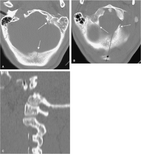 FIGURE 6-2. Type II occipital condyle fracture. A: Axial CT shows a left occipital fracture extending through the left occipital condyle (arrows). B: Axial CT of the same patient shows the left occipital fracture (black arrow) extending through the skull base bilaterally (white arrows). C: Left parasagittal CT multiplanar reformation shows no evidence of atlanto-occipital dislocation. |
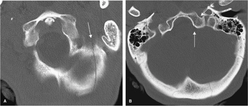 FIGURE 6-3. Type II occipital condyle fracture. A: Axial CT shows a left skull base fracture (arrow). B: Axial CT of the same patient shows the left skull base fracture extending through the left occipital condyle (white arrows). |
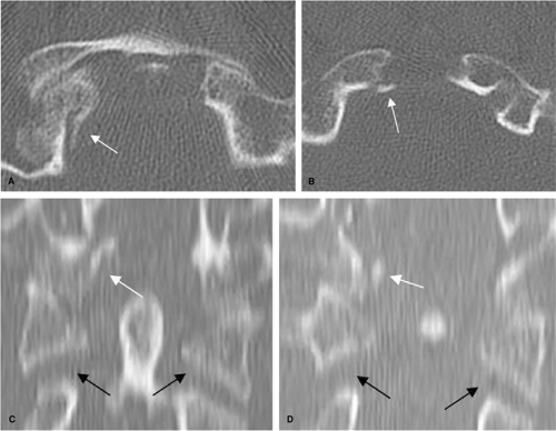 FIGURE 6-4. Type III occipital condyle fracture. A,B: Axial CT images demonstrate a right occipital condyle avulsion fracture with medial displacement of the fragment (arrows). C,D: Coronal CT multiplanar reformations show avulsion of the medial aspect of the right occipital condyle (white arrows). Note distraction between C1-2 (black arrows), indicating that the injury involves at least two levels. |
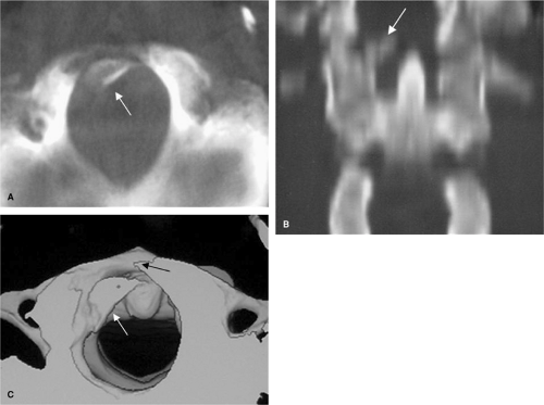 FIGURE 6-5. Type III occipital condyle fracture. A: Axial CT image demonstrates a right occipital condyle avulsion fracture with medial displacement of the fragment into the foramen magnum (arrow). B: Coronal CT multiplanar reformation shows avulsion of the medial aspect of the right occipital condyle (arrow) with ≫ 5 mm medial displacement of the avulsed fragment into the foramen magnum. C: Reformatted 3D-shaded surface superior axial view demonstrates the right condylar fracture with medial displacement of the avulsed fragment into the foramen magnum (white arrow). Note the extension of the fracture to the clivus (black arrow). |
Atlas (C1) Fractures
Fractures of the first cervical vertebra ring are generally related to axial loading and commonly occur in association with other injuries, including those of the occipital condyle and the axis. Neurologic compromise is relatively infrequent with fractures of the cervical vertebra C1 ring, presumably because the axial compression mechanism results in a burst configuration with expansion of the spinal canal.
Jefferson Fracture
The classic Jefferson fracture (JF), described in 1920 (23), is a four-point injury with fractures occurring at the junctions of the anterior and posterior arches with the lateral masses, the weakest structural portions of the atlas (C1) (Figs. 6-7, 6-8). However, CT has shown that a JF requires only one anterior and one posterior arch fracture, although any combination of anterior and posterior arch fractures may occur (24) (Fig. 6-7). Most commonly there are two fractures in the posterior arch (one on each side) and a single fracture in the anterior arch, off the midline (25). At times, there is a single fracture in each arch. A JF is created by sudden and direct axial loading on the vertex. The lateral articular masses of the atlas become compressed between the occipital condyles and the superior articular facets of the axis. By its nature, this is a decompressive injury because the bony fragments are displaced radially away from the neural structures (Figs. 6-9, 6-10). Although the typical JF behaves in a stable fashion, variant injuries patterns can be or are mechanically unstable (Fig. 6-12, Table 6-5). Lee and Woodring (26) described a group of patients with axial loading injuries with less than four-part fractures and with fractures through the ring in atypical locations.
Table 6-5 Jefferson Fracture | ||||||||||||||||||||||||||||||||
|---|---|---|---|---|---|---|---|---|---|---|---|---|---|---|---|---|---|---|---|---|---|---|---|---|---|---|---|---|---|---|---|---|
|
If there is a separation between the fracture fragments of the atlas by more than 6 to 7 mm, the injury is considered unstable because the separation implies disruption of the transverse atlantal ligament (TAL), which is a strong band that extend between the medial aspect of the C1 lateral masses and holds the dens against the anterior arch of C1. This fragment separation can be ascertained from the superior three-dimensional (3D) axial views, coronal CT reconstruction, or open-mouth anteroposterior (AP) odontoid view (Table 6-5). In all JF is important to carefully assess the atlanto-dental space to be sure that it does not exceed 3 mm in adult patients (Fig. 6-11). A greater distance would imply TAL tearing (27). JF are commonly associated with concurrent injuries of the
upper cervical spine, particularly the high and low dens fractures and hangman fracture.
upper cervical spine, particularly the high and low dens fractures and hangman fracture.
 FIGURE 6-6. Atlanto-occipital distraction injury. A,B: lateral radiographs of the cervical spine show increased separation between the basion and superior tip of the odontoid (black line in A) exceeding 12 mm. The occipital condyles (interrupted black line in B) are superiorly dislocated with respect to the superior surfaces of C1 (interrupted white line in B). |
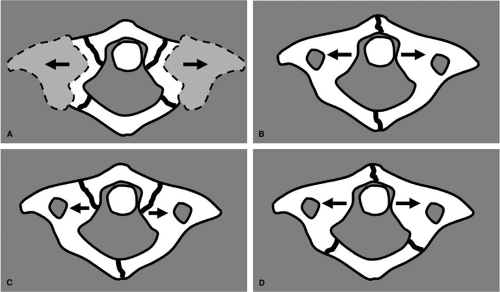 FIGURE 6-7. Jefferson fracture. The classic JF is a four-point injury with fractures occurring at the junctions of the anterior and posterior arches with the lateral masses, the weakest structural portions of the atlas (C1), with resultant bilateral offset or spreading of the lateral articular masses of C1 (A) (arrows indicate offset of lateral masses). However, CT has shown that JF require only one anterior and one posterior arch fractures (B), although any combination of anterior and posterior arch fractures may occur (C,D). Most commonly there are two fractures in the posterior arch (one on each side) and a single fracture in the anterior arch off the midline (D). (Harris JH. Jr, Mirvis SE. Vertical compression injuries. The Radiology of Acute Cervical Spine Trauma, 3rd ed. Baltimore: Williams & Wilkins; 1996:340-345; Landells CD, Van Pethegem PK. Fractures of the atlas: classification, treatment and morbidity. Spine. 1988;13:450-452.) |
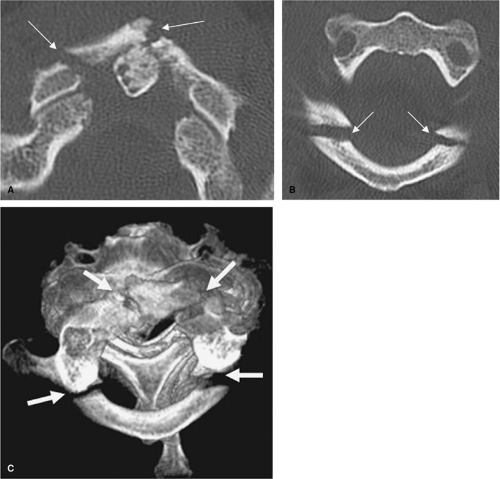 FIGURE 6-8. Jefferson fracture. A: Axial CT image at the level of the anterior arch of C1 demonstrates two anterior arch fractures (arrows). B: A second axial CT image obtained more inferiorly demonstrates bilateral fractures of the posterior arch of C1 (arrows). C: Reformatted 3D volume rendered superior axial view demonstrates bilateral anterior and posterior C1 arch fractures (arrows), with < 6-mm fragment displacement and posterior dislocation of the atlas. |
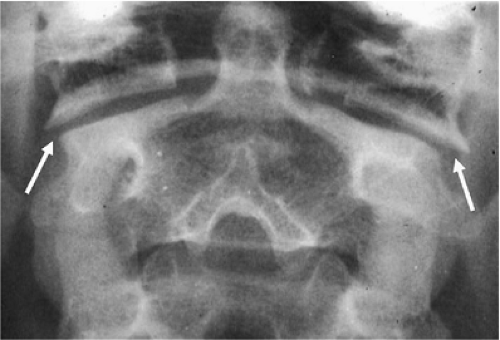 FIGURE 6-9. Jefferson fracture. AP open-mouth view demonstrates lateral displacement of the lateral masses of C1 bilaterally (arrows) in relation to the superior facets of C2 (compare to normal cervical spine in Fig. 5-15). |
Pitfalls in the diagnosis of the JF include clefts and aplasias in the atlas ring that simulate fractures; these are typically differentiated by smooth, well-defined corticated bone margins. In children younger than age 5, the ossification of the lateral mass of C1 often exceeds that of the ossification of C2, giving rise to what has been termed “pseudo spread” of C1 upon C2 (28, 29).
Lateral Mass (C1) Fracture
Fractures of the lateral mass of C1 usually occur as a result of a lateral tilt or an eccentric axial loading (Fig. 6-13). The fracture may be limited to the lateral mass of C1, or more commonly, occurs in association with occipital condyle fractures and/or fracture of the articular process of C2. The C1 lateral mass fracture is usually visible on
the open-mouth view; however, sometimes the abnormal cervico-cranial prevertebral soft tissue contour is the only sign of injury in plain films. A fracture of the lateral mass of C1 is considered unstable because the TAL is detached from the lateral mass.
the open-mouth view; however, sometimes the abnormal cervico-cranial prevertebral soft tissue contour is the only sign of injury in plain films. A fracture of the lateral mass of C1 is considered unstable because the TAL is detached from the lateral mass.
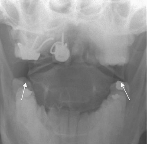 FIGURE 6-10. Jefferson fracture. AP open-mouth view demonstrates minimal asymmetric offset of C1 upon C2 bilaterally (arrows), left greater than right. |
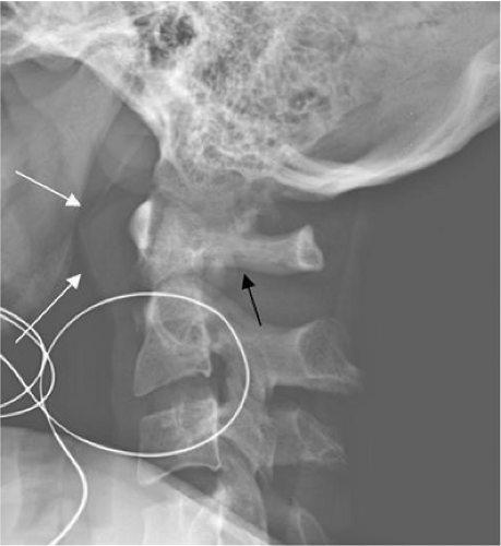 FIGURE 6-11. Jefferson fracture. Lateral radiograph shows soft tissue swelling anterior to C1 and the upper margin of C2 (white arrows). A fracture of the posterior C1 arch (black arrow), representing a part of a Jefferson fracture, is identified. Normal anterior atlantoaxial distance is noted. |
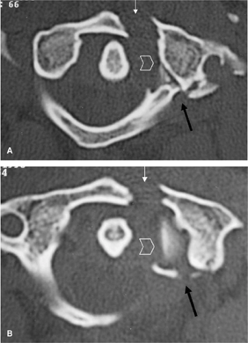 FIGURE 6-12. Atypical Jefferson fracture. A,B: Axial CT images show a displaced (≫ 7 mm suggesting instability) single fracture of the left anterior arch of C1 (white arrows) and left lateral comminuted fracture of the posterior atlas ring (black arrows). Avulsed fragments from the medial surface of the left lateral mass of C1 by the transverse atlantal ligament (TAL) are noted (open arrowhead). |
Isolated Fractures of C1
Isolated fractures of the anterior or posterior arch of C1 are usually stable (Figs. 6-14, 6-15); these injuries should be distinguished from the Jefferson bursting fracture and its variants. The most common isolated fracture of C1 is a bilateral vertical fracture through the posterior neural arch (30, 31, 32 and 33). This type of fracture is caused by hyperextension of the head on the neck, which compresses the neural arch of C1 between the occiput and the neural arch of C2. It is best demonstrated on the lateral view. It carries no risk of neurologic deficit. This fracture must be distinguished from developmental defects (Fig. 6-16).
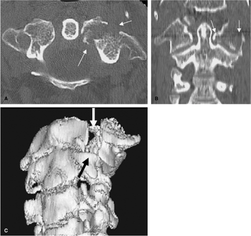 FIGURE 6-13. Lateral mass C1 fracture. A: Axial CT image shows a comminuted left lateral mass fracture of C1 (arrows) caused by lateral tilt. B: Coronal CT multiplanar reformation clearly demonstrates a comminuted fracture of the left lateral mass of C1 (arrows). C: 3D surface rendered frontal oblique view also demonstrates the left lateral mass of C1 fracture with fragment displacement (arrows). |
 FIGURE 6-14. Isolated fracture of the anterior arch of C1. A: Inferior-frontal and (B) frontal reformatted 3D CT. Shaded surface views demonstrate an isolated fracture of the anterior atlas arch (arrows). |
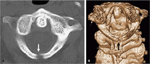 FIGURE 6-15. Isolated fracture of the posterior arch of C1. A: axial CT and (B) posterior-superior reformatted 3D CT. Shaded surface view demonstrate an isolated fracture of the posterior atlas ring (arrows). |
Horizontal fractures of the anterior arch of the atlas have been described (Fig. 6-17) (34, 35). These fractures are characteristically minimally displaced, best visualized on the lateral view, and often associated with dens fractures. Horizontal fractures result from avulsion mediated through the tendinous ligamentous insertion on the anterior tubercle by the anterior longitudinal ligament and the longus colli muscle. These lesions may be missed on axial CT images, but they are readily visualized on the lateral radiographs and sagittal CT reconstructions.
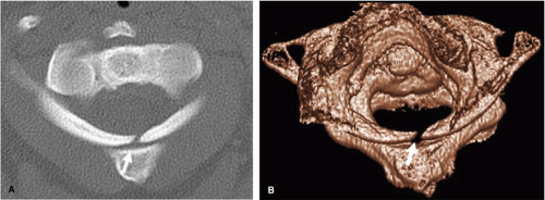 FIGURE 6-16. Partial nonossification of posterior atlas ring. A: Axial CT image and (B) volume rendered 3D reconstruction superior view show smooth margins of a partially nonossified posterior atlas ring (arrows). |
Axis (C2) Fractures
About 15% to 20% of cervical fractures involve the axis, 40% of which are associated with head injuries and 18% with other cervical spine injuries (36, 37, 38 and 39). Approximately 25% are hangman fractures, over half (58%) are odontoid fractures, and the remainder are miscellaneous fractures involving the body, lateral mass, or spinous process (32, 40, 41).
Hangman Fracture (Traumatic Spondylolisthesis of C2)
Hangman fractures are variously known as traumatic spondylolisthesis of the axis (C2), fractures of the neural arch of the axis, or fractures of the ring of the axis. Schneider et al. (42) noted that this injury is identical to that created by judicial hanging (43, 44), and thus the designation of the hangman fracture (42, 45, 46). In actuality,
the hangman fracture is a group of injuries with variable mechanisms that have different radiographic appearances (Table 6-6). The most common form of this injury results from extension combined with axial loading. The full force of acute hyperextension of the head on the neck is transmitted through the pedicles of C2 onto the apophyseal joints (45). The weakest points in this chain are the interarticular segments of the pedicle. Thus, the arch of C2 is fractured anterior to the inferior facet (45). These injuries are commonly sustained in automobile accidents as the chin or forehead encounters the steering wheel or dashboard, forcing the head into hyperextension. Hangman fracture is a bilateral fracture through the pars interarticularis of C2. The pars interarticularis is found between the superior and inferior articular processes of C2. Spinal cord damage is uncommon, despite frequent significant fracture displacement, due to the wide spinal canal at this level.
the hangman fracture is a group of injuries with variable mechanisms that have different radiographic appearances (Table 6-6). The most common form of this injury results from extension combined with axial loading. The full force of acute hyperextension of the head on the neck is transmitted through the pedicles of C2 onto the apophyseal joints (45). The weakest points in this chain are the interarticular segments of the pedicle. Thus, the arch of C2 is fractured anterior to the inferior facet (45). These injuries are commonly sustained in automobile accidents as the chin or forehead encounters the steering wheel or dashboard, forcing the head into hyperextension. Hangman fracture is a bilateral fracture through the pars interarticularis of C2. The pars interarticularis is found between the superior and inferior articular processes of C2. Spinal cord damage is uncommon, despite frequent significant fracture displacement, due to the wide spinal canal at this level.
Table 6-6 Hangman Fracture (Traumatic Spondylolisthesis of C2) | ||||||||||||||||||||||||
|---|---|---|---|---|---|---|---|---|---|---|---|---|---|---|---|---|---|---|---|---|---|---|---|---|
|
Effendi et al. (47) described a classification of the hangman fracture that includes three types. Type I fracture is defined as an isolated “hairline” fracture, with < 3 mm fragment displacement, < 15-degree angle at the fracture site, and normal C2-3 disc space (Figs. 6-18, 6-19, 6-20). The mechanism of this injury is hyperextension with concomitant axial loading and a force sufficient enough to cause the fracture but not enough to disrupt the ALL, PLL, or the C2-3 disc. These lesions are often subtle and easily missed radiographically. Commonly associated concomitant injuries are C1 posterior arch fractures, C1 lateral mass fractures, and odontoid fractures. Type II injuries are characterized by more than 3 mm of fragment displacement (Fig. 6-21) or more than a 15-degree angle at the fracture site and an abnormal C2-3 disc space. The mechanism of this injury is hyperextension with concomitant axial loading, followed by flexion with concomitant axial compression. The resultant injury pattern is bilateral pedicle fractures with slight disruption of the ALL and significant disruption of the PLL and C2-3 disc.
Levin and Edwards (48), modifying the work of Effendi et al. (47), introduced a new subtype of this fracture, type IIA (Fig. 6-22). Type IIA fractures demonstrate no anterior displacement but do show severe angulation. The mechanism for this injury is flexion with concomitant distraction. The resultant injury pattern is bilateral pedicle fractures with C2-3 disc disruption and some degree of insult to the PLL. This is an unstable fracture. Radiographs taken while the patient is in cervical traction demonstrate an increase in the C2-3 posterior disc space.
Type III consists of the changes that characterize type II injury plus a C2-3 articular facet dislocation (Fig. 6-23). In type III there is displacement of the body of the axis forward in the flexion position associated with disruption of the facet joints of C2-3, which are either dislocated or locked. In the series of Effendi et al. (47), 65% of hangman
fractures were type I, 28% were type II, and 7 % were type III. Type I injuries are considered stable, type II and III injuries are considered unstable (Table 6-6).
fractures were type I, 28% were type II, and 7 % were type III. Type I injuries are considered stable, type II and III injuries are considered unstable (Table 6-6).
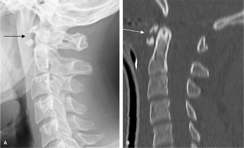 FIGURE 6-17. Hyperextension avulsion (horizontal) fracture of the anterior arch of C1. A: Lateral radiograph and (B) sagittal CT multiplanar reformation show an avulsion fracture of the anterior atlas arch (arrows) and prevertebral soft tissue swelling. |
 FIGURE 6-18. Type I hangman fracture. A: Lateral radiograph and (B) type I hangman fracture illustration demonstrate a nondisplaced subtle fracture line through the pars interarticularis of the axis (red arrow) and posterior offset of the C2 spinolaminar line (black line/yellow arrow). The second intervertebral disc is intact (green arrow). |
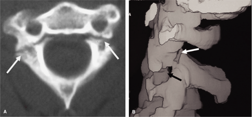 FIGURE 6-19. Type I hangman fracture. A: Axial CT demonstrates the bilateral pars fracture of C2 (white arrows) without significant fragment displacement. B: CT reformatted 3D surface rendered lateral view shows the nondisplaced subtle fracture line through the pars interarticularis of the axis (white arrows) and normal C2-3 disc space (black arrow). |
“Atypical” traumatic spondylolisthesis of C2, even though quite common, refers to a lesion in which one (unilateral) or both (bilateral) fractures occur in the coronal plane of the middle column of the axis body (5) (Figs. 6-24, 6-25). In this variant hangman fracture, the involved component of the posterior vertebral body may undergo retropulsion and may contribute to cord injury. The clinical significance of identifying the atypical hangman fracture relates to the approximately 30% higher incidence of paralysis than occurs with typical Effendi type I and II injuries.
 FIGURE 6-20. Type I hangman fracture. Lateral cervical radiograph demonstrates fracture through the pars interarticularis (white arrow) without extension to the “C2 ring.” There is slight anterior displacement of the axis body without angulation (black arrow). |
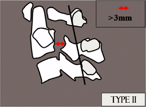 FIGURE 6-21. Type II hangman fracture. Illustration demonstrates ≫ 3 mm of fragment displacement and posterior offset of the C2 spinolaminar line. |
Odontoid Fractures
Fractures of the odontoid process arise as a result of diverse mechanisms. The traditional classification of dens
fractures proposed by Anderson and D’Alonso (49) consists of three types based upon the location of the fracture site with respect to the dens (Fig. 6-26, Table 6-7). Type I is described as an oblique fracture of the superior lateral aspect of the dens, avulsed by the alar (“check”) ligament; this is an extremely uncommon injury, occurring in < 4% of odontoid fractures (Fig. 6-27). Type I injuries may indicate atlanto-occipital dislocation and should be regarded as a sign of instability (50). The type II fracture, also referred to as a high odontoid fracture by Gehweiler et al. (51) and Alexander et al. (52), is a fracture at the base of the dens (Figs. 6-28, 6-29, 6-30, 6-31, 6-32, 6-33, 6-34, 6-35, 6-36) (Figs. 5-1 and 5-22). In 1988 Hadley et al. (53) introduced a comminuted subtype of this fracture, type IIA. Since then, several authors have recommended a more aggressive surgical approach in the treatment of this subtype. However, only a few cases of comminuted type II fractures have been reported. Koivikko et al. (54) in 2003 reviewed 26 type II fractures imaged by multislice CT. Subtle comminution of the fracture was observed in 12 of the cases. They concluded that subtle comminution in type II odontoid fractures is seen more commonly than previously reported in the literature when imaged by multislice CT. The type III fracture, also referred to as a low
odontoid fracture by Gehweiler et al. (51) and Alexander et al. (52), is an oblique fracture of the superior portion of the axis body caudal to its junction with the base of the dens (Figs. 6-33, 6-34). Type II injuries are the most common injury, comprising 60% of dens fractures (55). Both acute and un-united type II odontoid fractures result in atlantoaxial instability because the proximal (cephalad) fragment and the atlas constitute a single unit (Figs. 6-32, 6-36). Dens fractures are frequently associated with fractures of the face and mandible, Jefferson fractures (Fig. 6-35), and extension teardrop fractures. Weisskopf et al. (56) compared four different radiological diagnostic methods in the analysis of odontoid fractures. Thirty-one patients with odontoid fractures were investigated using standard anteroposterior and lateral radiographs, conventional tomography, axial computerized tomography, and two-dimensional reconstruction in the sagittal and the coronal planes. They found that CT examination with sagittal and coronal reconstructions was equivalent to conventional tomography in diagnostic accuracy and was also less time consuming. They concluded, therefore, that CT could replace conventional tomography.
Related posts:
 Pathophysiology of Spinal Cord Injury
Plain Film Radiography and Computed Tomography of the Cervical Spine: Part I. Normal Anatomy and Spinal Injury Identification
Imaging of Thoracolumbar Spinal Injury
Magnetic Resonance Imaging of Acute Spinal Trauma
Postoperative Spinal Imaging
Imaging of Pediatric Spinal Injury
Pathophysiology of Spinal Cord Injury
Plain Film Radiography and Computed Tomography of the Cervical Spine: Part I. Normal Anatomy and Spinal Injury Identification
Imaging of Thoracolumbar Spinal Injury
Magnetic Resonance Imaging of Acute Spinal Trauma
Postoperative Spinal Imaging
Imaging of Pediatric Spinal Injury
Stay updated, free articles. Join our Telegram channel

Full access? Get Clinical Tree


