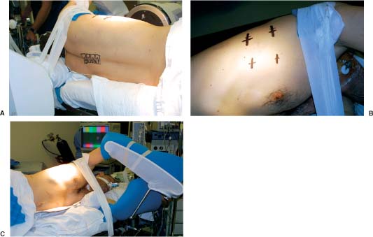
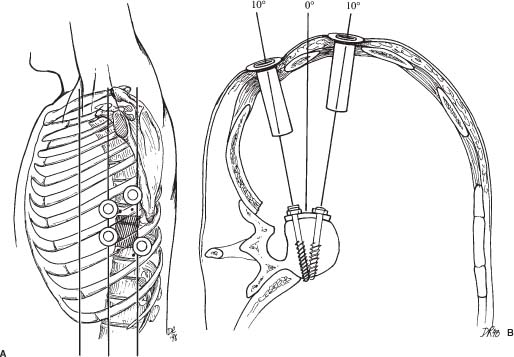
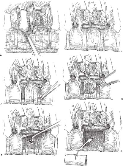
31 Video-assisted thoracoscopic surgery has been used extensively by cardiothoracic surgeons to treat a variety of pathologies that involve the thoracic cavity. This minimally incisional approach has been associated with substantial clinical benefits in the treatment of thoracic pathology, including reduced postoperative pain, shortened stays in the intensive care unit and hospital, shortened recovery times, faster returns to activity, and reduced complication rates compared with thoracotomy.1-4 It is a natural extension of the progress achieved in thoracic surgery to apply this technique to the treatment of pathology affecting the anterior thoracic spine. The initial techniques for thoracic discectomy using a microsurgical thoracoscopic approach have been reported.5-7 This chapter describes specific surgical techniques for thoracic vertebrectomy, decompression of the thoracic spinal cord, and spinal reconstruction using a microsurgical thoracoscopic approach, focusing on the relevant anatomy and operative techniques. Patients are positioned in a lateral decubitus position with an axillary roll padding the dependent axilla. The lower leg is flexed, and the knees and bony prominences are padded with pillows and foam padding. A double-lumen endotracheal tube is used to deflate the lung ipsilateral to the side of access to the spine. An incision is marked on the chest wall for a potential thoracotomy, and the position of the scapula is outlined in case open access is needed. Four separate skin incisions (15 to 20 mm long) are marked over the intercostal spaces for insertion of the thoracoscopic working portals. The first portal is positioned in the anterior or middle axillary line. Subsequent portals are positioned over the anterior, middle, or posterior axillary lines in separate intercostal spaces. Flexible portals (15 to 20 mm diameter) are inserted into the intercostal spaces. Rigid portals are avoided when possible because they have been associated with postoperative intercostal neuralgia.2-4 The portals are distributed in several different locations in the chest wall to “triangulate” the portal localizations, centered over the spinal lesion. The portals are separated by enough space on the surface of the chest to avoid “fencing” of the tools used for the dissection. The first portal is inserted and the rigid rod-lens endoscope is introduced through it. The endoscope is used to directly visualize insertion of the subsequent portals. The additional portals are needed for lung retractors, suction, irrigation, and tissue dissection tools. The portals are inserted in a manner similar to the insertion of a chest tube. A 15- to 20-mm skin incision is made parallel to the superior margin of the rib. The intercostal muscles and parietal pleura are penetrated with a tissue clamp. The clamp is spread apart and withdrawn to dissect a tissue space for the portal. The thoracoscopic portals are inserted through the intercostal spaces adjacent to the superior surface of the ribs to avoid the neurovascular bundle. The portals are inserted with a blunt-tipped trocar to guide them into the chest. The tips of the portals penetrate the thoracic cavity. The surfaces of the portals have a cuff that is sutured to the skin to anchor their position during the operation. The portals are strategically positioned on the chest wall using fluoroscopic guidance to permit trajectories for inserting screws into the spine (Figs. 31-1 and 31-2). FIGURE 31-1 Photographs of patient positioning for thorascopic corpectomy. (A) Posterior view of the patient in a lateral decubitus position. The involved vertebrae are identified using a C-arm, and the locations of the vertebrae are marked with a surgical marking pen. (B) The portal incisions are marked on the lateral chest wall, using fluoroscopy. (C) The arm is abducted and supported with an airplane splint. The dependent axilla is padded with an axillary roll. A right- or a left-sided approach is used, depending on the location and eccentricity of the pathology and on the regional anatomy. If the pathology is in the center of the spinal canal, a right-sided approach is preferred because more working space is available over the spinal surface behind the azygos vein compared with the aorta. A thoracoscopic approach can access the second through the 12th thoracic vertebrae (i.e., from the T1–2 to the T11–12 disc spaces). The upper thoracic levels are accessed by abducting the patient’s arm and cradling it in an airplane splint. The most cephalad portals can be placed into the third and fourth intercostal spaces within the axillae. The lower thoracic (T11 and T12) levels can be accessed by retracting the hemidiaphragm caudally with an endoscopic fan retractor. The left side of the lower thoracic spine is usually easier to expose because the liver caused the right hemidiaphragm to be higher. The middle thoracic levels can be exposed from either side, depending on the location of the pathology and on the position of the thoracic duct, artery of Adamkiewicz, azygos vein, aorta, and other structures. The ipsilateral lung is deflated using a double-lumen endotracheal tube. The patient is rotated anteriorly to allow the atelectatic lung to fall away from the surface of the spine. If the lung partially covered the spinal surface after maximally tilting the table, a blunt-tipped, fan-shaped retractor is used to gently hold the lung away from the spine. The first rib is palpated with a tool; however, the first rib can seldom be identified visually. The second rib is the first rib visible within the thoracic apex. After the apical ribs have been identified, the ribs are sequentially counted distally to identify the level of the spinal pathology. Each rib articulates with the cephalad portion of the corresponding vertebrae. For example, the 11th rib articulates with the T10–T11 disc space and with the transverse process and pedicle of the T11 vertebrae. The spinal level is identified definitively by placing a long needle through the portal into the disc space and obtaining static radiographs or fluoroscopic images. Anteroposterior views are required to identify the level intraoperatively. Lateral views do not provide the perspective needed to count the ribs and vertebrae accurately. FIGURE 31-2 (A) Lateral and (B) cross section of the thorax. The portals are positioned in a coaxial trajectory with the intended trajectory of the bolts and screws. Endoscopic visualization is facilitated using a high-resolution rigid rod-lens endoscopic system. The thoracoscope is a 10-mm diameter rigid tube that contained a rod-lens system that is connected to a video camera and video monitor display system. Illumination and magnification are provided. Most thoracoscopes have a magnification of 20× and use xenon or halogen light sources. We use a three-chip, high-resolution endoscope system. Video monitors are positioned on both sides of the head of the operating table to allow the surgeon, assistants, and nurses to visualize the surgery as it progresses. A 0- or 30-degree angled lens is useful for spinal thoracoscopy. Warm irrigation is used throughout the operating procedure to avoid fogging of the thoracoscope lens. A sterile defogging solution Fog Reduction/Elimination Device (FRED; Dexide, Fort Worth, TX) is applied to the lens periodically to maintain a clear, sharp image during surgery. Table-mounted scope-holding devices are used to maintain the endoscope and retractors in a stable, yet adjustable position throughout the operation. A voice-activated robotic arm is used to hold and move the endoscope for precise positioning (AESOP; Computer Motion, San Golota, CA). The working distance from the chest wall to the surface of the spine ranges from 14 to 30 cm, depending on the patient’s size and the position of insertion of the portal. Therefore, long adaptations of soft tissue and bone dissection tools are needed to perform the surgery. Most of the soft tissue dissection tools and hemostatic agents are available for use in laparoscopy, thoracoscopy, or open surgery. The bone dissection tools and drills have been modified from spine tools of standard length. All of the tools are narrow enough to fit through the thoracoscopic portals (10 to 20 mm) yet are long enough to dissect the spine and paraspinal tissues. Various hemostatic tools, similar or identical to tools used in open procedures, are available. Bipolar cautery forceps, monopolar cautery blades, bipolar and monopolar cautery scissors, and monopolar tissue forceps are used to coagulate blood vessels to obtain hemostasis during the tissue dissection. Straight and right-angled vascular hemoclips are used to ligate the segmental vessels before they are sectioned. The segmental vessels are always clamped with hemoclips because they communicate directly with the great vessels. Endoscopic Avitene, Gelfoam, Nu-Knit™ (Johnson & Johnson, Arlington, TX), and cottonoid paddies are used for epidural hemostasis. The end of the string of the cottonoid is secured with a hemostat so the cottonoid is not lost within the thoracic cavity. Endoscopic peanut dissectors are used to apply bone wax to control bone bleeding. The peanut dissectors are also used to mobilize soft tissue from the surface of the spine or to gently retract tissue. A sponge stick and a thoracotomy tray are always opened and immediately available on the operating field in case a vascular complication occurs. The sponge stick is narrow enough to be inserted through an endoscopic portal; it is prepared for the gentle tamponade of large blood vessels until a thoracotomy can be performed. If needed, the surgeon must be prepared to perform an immediate thoracotomy. Fan retractors are expandable and collapsible tissue retractors with rounded, blunt blades. These retractors are used to gently retract the lung medially away from the surface of the spine or to retract the diaphragm. Endoscopic tissue forceps, right-angle tissue clamps, scissors (endoshears), bipolar cautery, Babcock forceps, irrigation and suction devices, and other endoscopic tools are used for tissue dissection. Bone graft impactors, osteotomes, Cobb periosteal elevators, 45- and 90-degree angled Kerrison rongeurs, disc rongeurs, Leksell rongeurs, straight and curved curettes, Penfield instruments, and nerve hooks are used for the spine dissection. The endoscopic spine tools are commercially available for endoscopic spine surgery (Medtronic Sofamor Danek, Memphis, TN). The spine tools have calibrated markings along their shafts at 1-cm increments to help judge the depth of the tools during dissection. Long attachments for high-speed air drills (Midas Rex®, Fort Worth, TX) are used for the bone dissection. A pistol-grip attachment is used to stabilize the drill. The surgeon uses two hands to grasp the drill outside the chest wall. The drill is also stabilized against a portal in the chest wall for a third point of fixation to allow precise control of the drill. The R attachment is used with small cutting bits (size 8) and rounded cutting burs (sizes 31, 32, and 33). These drill attachments have a 25-cm-long shaft that readily reaches the surface of the spine and allow enough room outside the chest to solidly anchor and control the drill handpiece. These techniques with a high-speed drill provide accurate, reliable fine control of the tip of the drill. The level of the pathology and the adjacent ribs are identified visually and radiographically. The heads of the ribs adjacent to the pathology are marked with monopolar cauterization to ensure accurate identification. A needle is inserted into the disc spaces for localization. Once the level of pathology is identified, the pleura is dissected to expose the spine. The pleura is elevated from the spine with a pleural dissector. Sharp dissection with microscissors is also used to divide the pleura. The segmental artery and vein are identified at the midportion of the vertebral body, halfway between each disc space (Fig. 31-3A). These segmental vessels are mobilized and isolated with a nerve hook. Hemoclips are applied to the proximal and distal portions of the vessels, and the vessels are cut between the hemoclips. The rib heads and proximal 1- to 2-cm of the ribs adjacent to the involved vertebrae are removed to expose the pedicles of the vertebrae (Fig. 31-3A,B). The proximal ribs are freed from the soft tissue attachments by detaching the intercostal muscles superiorly and inferiorly and freeing the neurovascular bundle from the inferior margin of the rib. A circumferential subperiosteal dissection of the proximal rib is performed using Cobb periosteal elevators and right-angled rib dissectors. The neurovascular bundles are easily dissected from the undersurface of the rib. Bleeding from the intercostal vessel is readily controlled with bipolar cauterization. The costotransverse and costovertebral ligaments are sectioned sharply using Cobb periosteal elevators and an angled rib dissector. The rib head and proximal rib are removed completely to allow clear identification of the nerve root as it exits the neural foramen and to allow access to the pedicle and dorsal disc space. The pedicle is a key landmark overlying the lateral aspect of the spinal canal. The pedicles are identified visually and by palpation. The pedicles are removed using a Kerrison rongeur. Removing the pedicle allows lateral exposure of the dura and spinal cord, with early identification of the thecal sac for safety during the operative procedure (Fig. 31-3A,B). Epidural venous bleeding is controlled with bipolar cauterization, Avitene, Flowseal, (Baxter Healthcare, Fremont, CA) or Gelfoam. After the pedicles are resected and the dura is identified, discectomies are performed to define the superior and inferior boundaries of resection of the vertebrae (Fig. 31-3C). The annulus is incised with a Cobb periosteal elevator. The disc material is loosened with curettes and removed with disc rongeurs. The vertebrectomy is performed using osteotomes, Leksell and Kerrison rongeurs, curettes, and highspeed drills. A ball-shaped cutting burr (R-31, -32, or -33) is used to create a large cavity in the center of the vertebrae (Fig. 31-3D). This cavity creates working space to dissect compressive pathology away from the dura. The posterior cortex of the vertebrae, the posterior longitudinal ligament, and compressive pathology or bone adjacent to the spinal canal are removed with fine cutting burrs (R-8), Kerrison rongeurs, and small, angled curettes (Fig. 31-3E). The sequence of operative techniques closely resembles those used for an open thoracic vertebrectomy; however, longer tools are required, and unique strategies are needed to manipulate the tools, to work within the restricted trajectories for tissue dissection, to maintain adequate thoracoscopic visualization of the spinal surface, to minimize tissue debris, and to work within a constrained visual field. The fusion bed is prepared by removing the disc material and cartilaginous end plates from the distal ends of the vertebrectomy site. With a periosteal elevator or drill, the bony end plates are decorticated and contoured to a flat surface to fit flush with the bone graft. The vertebrae are reconstructed and fused using autologous or allograft bone struts or titanium mesh cages. The vertebrectomy defect is measured with a sterile plastic surgical ruler. The ruler is inserted into the vertebrectomy bed to measure its width, depth, and height. We prefer a tricortical iliac crest graft or a whole shaft humerus allograft filled with the patient’s own bone to reconstruct the vertebra (Fig. 31-3F). The bone grafts are measured and sized so that they fit precisely within the vertebrectomy defect, with a large contact area of bone fitting flush and compressed against the adjacent end plates. This strut is used to bear compressive axial loads. The bone grafts are inserted into the chest “end on” through a 20-mm flexible endoscopic portal. Occasionally, one of the intercostal incisions must be lengthened to fit a wider bone graft into the thoracic cavity. After the graft is inserted through the portal into the thoracic cavity, the bone graft is grasped with a Babcock clamp and positioned over the vertebrectomy defect. The relationship of the bone graft to the dura is visualized directly during the insertion of the bone graft so it does not compress the spinal cord. Bone-graft impactors and mallets are used to tamp the bone graft firmly into position so that the ends of the graft are compressed securely against the upper and lower end plates of the adjacent vertebrae. Methylmethacrylate can also be used to reconstruct the vertebral bodies. If the patient’s life expectancy is limited, this polymer can be used to reconstruct vertebrae destroyed by aggressive tumors. This technique was described by Errico and Cooper8 for open anterior approaches to the thoracolumbar spine to anchor a methacrylate strut. The methacrylate is anchored deeply into the adjacent normal vertebrae to prevent the methylmethacrylate from loosening. A Silastic tube is sized slightly longer than the vertebral defect. The end plates of the adjacent uninvolved vertebrae are removed, and holes are made in the adjacent vertebrae with curettes to telescope a Silastic tube into the adjacent vertebrae (Fig. 31-4). A hole is made in the middle of the Silastic tube to inject the methylmethacrylate. A 16-gauge or wider-diameter long needle or a long plastic catheter is used to inject cranioplasty methylmethacrylate into the tube. The methylmethacrylate is injected so that it completely fills the plastic tube and extrudes beyond the ends into the cancellous bone of the adjacent vertebra. To prevent the methylmethacrylate from setting in the syringe or catheter, the polymer is injected immediately after mixing it briefly while still liquefied. The methylmethacrylate is injected into the Silastic tube around the ventral and lateral surfaces of the tube. The Silastic tube is countersunk into the adjacent vertebral bodies and is fully filled with methylmethacrylate to anchor the methylmethacrylate adequately into the adjacent vertebra.
Thoracoscopic Corpectomy and Spinal Reconstruction
 Operative Techniques
Patient Positioning
Portal Placement

Spinal Access
Localization of Level

Video-Assisted Thoracoscopic Equipment
Thoracoscopic Surgical Instrumentation
Hemostatic Tools
Endoscopic Soft Tissue Dissection Tools
Endoscopic Spine Tools
Technique of Thoracoscopic Vertebrectomy
Vertebral Body Reconstruction
Stay updated, free articles. Join our Telegram channel

Full access? Get Clinical Tree


