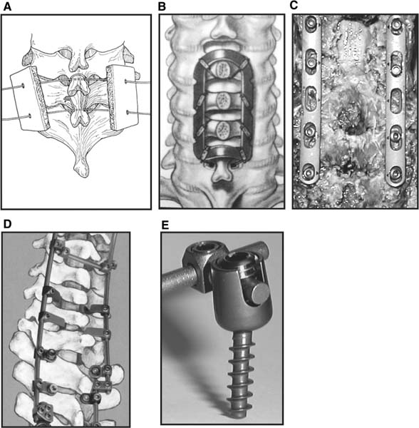
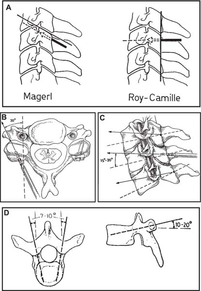
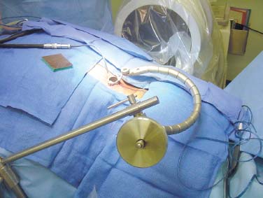
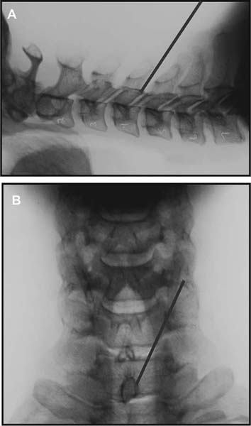
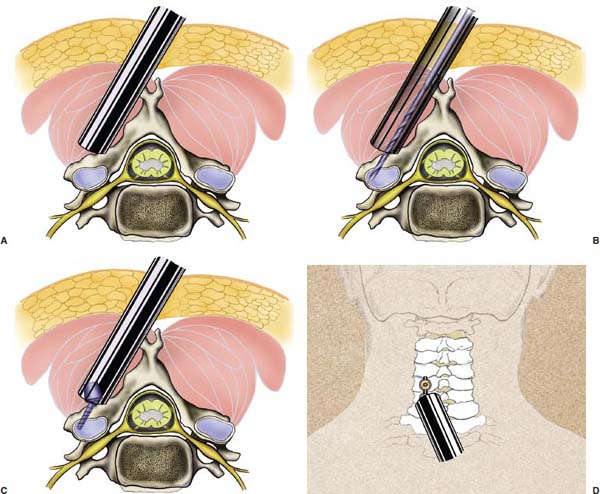
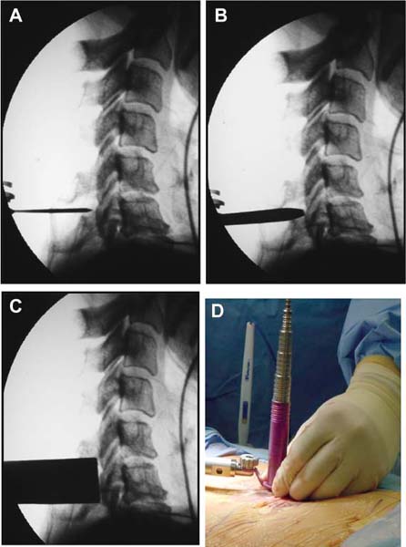
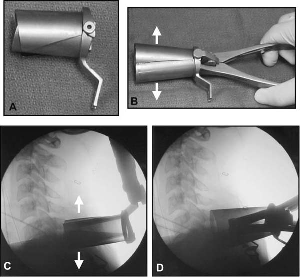
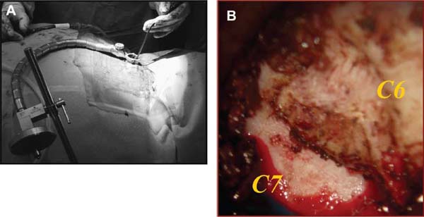
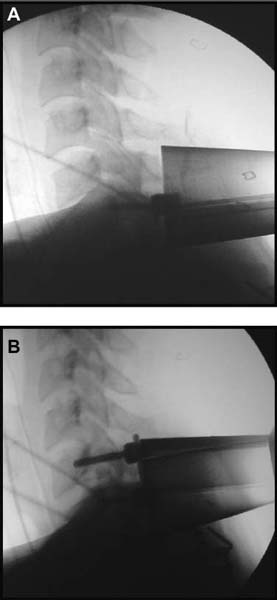
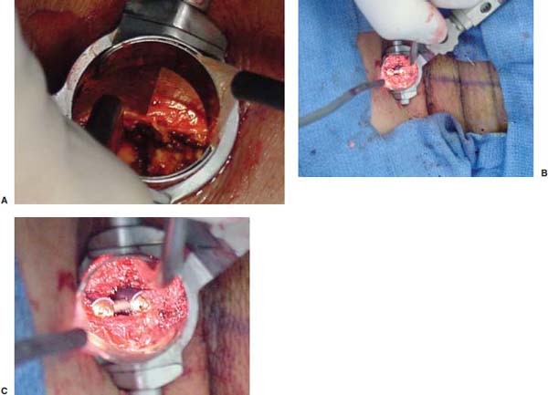
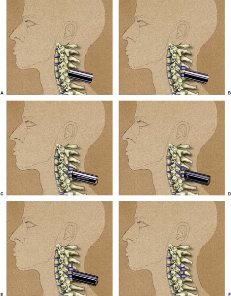
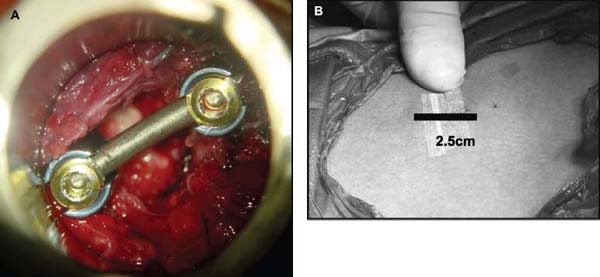
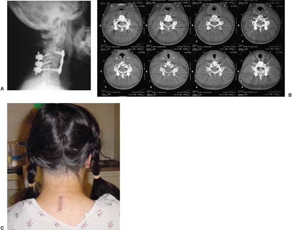
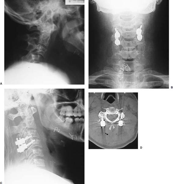
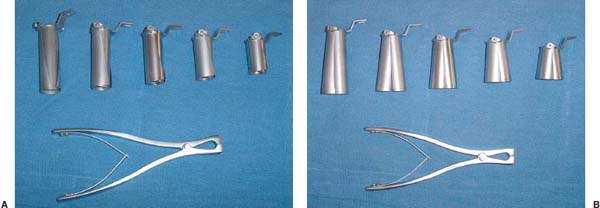
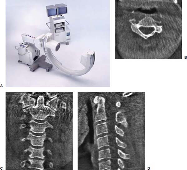
Several internal fixation techniques have been developed for the posterior fixation of the subaxial cervical spine.1 These techniques include the use of interspinous wiring with bone graft, the use of metallic plates affixed to the lateral masses with screws, interlaminar (i.e., Halifax) clamps, Daab plates, hook plates, and hook and rod constructs (i.e., Harrington) for long facet fusions.2 McAfee and Bohlman’s interspinous wiring techniques in multilevel fusions was more commonly used. In this technique, three wires are used and passed through holes made at the spinolaminar junction and around the rostral border of the rostral spinous process (Fig. 9–1A).3–5 Biomechanical studies have verified the strength of this construct, and case reviews have described excellent union with this technique.6–9 In cases of severe posterior column injury, the dorsal spinolaminar sites are also often unavailable for use, and Luque rectangles with facet wiring were often used (Fig. 9–1B). Advantages of this triple-wire technique included the ability to bridge large dorsal column defects (e.g., after tumor resections), afford segmental fixation at every level, and provide greater torsional and rotational stability.10,11 In 1979, Roy-Camille and co-workers described a technique of cervical posterior instrumentation in which plates were fixed with screws to the lateral processes of the cervical spine (Fig. 9–1C).12,13 This technique proved to be significantly stronger on biomechanical testing.14–16 Subsequent authors described a 95 to 100% fusion rate with this technique when combined with autogenous bone grafting.17–19 Anderson et al20 went on to modify Roy-Camille’s screw trajectory of dead-on center in the facet aiming inward to one where the screws are started 1 mm medial to the facet center and angled 30 degrees upward and 10 degrees outward. In the cervical spine, the screws are placed into the lateral masses, but the lateral masses evolve into the transverse processes in the thoracic spine, which may be insufficiently strong for screw placement.21–25 Dissatisfaction with the quality of lateral mass screw fixation at C7 and T1 subsequently led several groups to use lower cervical spine and thoracic pedicle fixation for several spinal disorders.1,2,26–32 In a calf model, Kotani et al33 compared several midcervical reconstruction systems and found that transpedicular screws increased the stability of fixation more than any of the other constructs. Newer instrumentation systems use two rods and variable screw islets at each level. These include Cervi-Fix (Synthes; Paoli, PA), StarLock (Fig. 9–1D) (Synthes), Summit (Depuy Acromed; Raynham, MA), and Vertex (Medtronic Sofamor Danek; Minneapolis, MN) (Fig. 9–1E). These systems vary by the angulation of their screws and in the degree of the constraint placed at the screw-rod interface. The polyaxial tulip or islet connectors of the screws are able to angle medially, laterally, and straight, with varying degrees of rotational freedom in each direction. As such, segmental fixation is more easily achieved via a top-loading approach, thereby making the possibility of minimally invasive posterior cervical fixation possible. Minimally Invasive Rationale and Evolution The past decade has witnessed an explosion of minimally invasive surgical techniques. In particular, there has been great excitement in the field of spinal surgery over minimal access technology due to the significant approach-related morbidities encountered by spine surgeons. Open surgery of the posterior spine requires stripping of muscles and ligaments simply for bony exposure. In the cervical and lumbar spine, this subperiosteal dissection devitalizes muscles and detaches key muscular and ligamentous insertions, disrupting the posterior musculoligamentous dynamic tension band. These drawbacks serve as the impetus driving minimally invasive surgery of the posterior spine. FIGURE 9–1 Numerous posterior cervical fixation techniques have been used with varying degrees of success over the years. One of the earliest was the interspinous triple-wire technique (A) popularized by Bohlman and colleagues. Sublaminar wiring was similarly commonly used and could be combined with a Luque-type construct for additional rigidity (B). Popularity of these semi-rigid constructs was eventually supplanted by the use of posterior lateral mass screw-plate fixation (C). The original unconstrained lateral mass screw-plate systems have since been supplanted by more rigid screw-rod and polyaxial screw-rod constructs (D,E). As already summarized, decompressive and fixation techniques of the posterior cervical spine have been well established for a variety of indications, including trauma, tumor, infection, degenerative disease, arthritides, and deformity.34–36 Often, however, the extensive dissection and stripping of the posterior musculature and ligaments are far greater than the actual size of the pathology. Indeed, the superficial and musculoligamentous exposure is often three to four times the size of the actual working target area. As a consequence of such iatrogenic injury, the popularity of some procedures has been limited because the postoperative disability from the approach often exceeds the intensity of the patient’s preoperative symptoms. As one such example, the effectiveness of posterior cervical laminoforaminotomy for decompression of the lateral recess and neural foramen has been well documented in numerous publications over the last four decades.37–40 For cases of isolated radiculopathy from either a lateral disk or an osteophyte, 93 to 97% of patients experienced symptomatic improvement by simply freeing the nerve root via decompressive laminoforaminotomy and removal of the disk and/or osteophyte.38,41,42 Enthusiasm for the operation was tempered by the significant cervical muscular pain and spasm that often followed. The use of wider incisions for adequate visualization and the need for significant paraspinous muscle dissection were blamed for this postoperative pain syndrome that resulted in a slower recovery course. Microendoscopic foraminotomy (MEF) represents the modern evolution of the classic operation with a minimally invasive approach and high-magnification direct endoscopic visualization.43 Developments in percutaneous surgical access, optical technology, neuroanesthetic techniques, and noninvasive imaging modalities have brought posterior foraminotomy into a new millennium of spinal surgery. By minimizing the amount of tissue trauma and muscle injury, the MEF procedure overcomes the limited visualization, postoperative pain, muscle spasm, and prolonged disability that served to limit the open foraminotomy operation. It is most important that several authors have consistently demonstrated the ability of the MEF operation to achieve the same clinical results as that of the classical open procedure44 with far less postoperative pain and shorter functional recovery times. Through the same corridor of tubular access, the lateral masses of the posterior cervical spine are readily visualized. Two adjacent lateral masses can typically be accessed through a 20 or 22 mm working portal. With the advent of some of the newer types of expandable access portals, including FlexPosure (Endius; Plainville, MA) and Xpand (Medtronic Sofamor Danek), up to three lateral masses can be instrumented through a single exposure. This led us to begin placement of top-loading polyaxial screws through the tubular portals for the purposes of posterior cervical lateral mass fixation. In our experience, the first such case was that of a 35-year-old male who suffered from a unilateral jumped facet with persistent radicular numbness and pain. A single 18 mm working portal was docked over the perched facet complex that was then drilled out and realigned intraoperatively. Local bone from the lamina, spinous process base, and facet was then packed into the denuded joint space. A short AO fragment plate was then placed into position and fixated with two 14 mm unicortical screws. At 1 year, no motion was demonstrated at this C5–C6 segment on flexion-extension films as measured at the spinous process tips.45 To our knowledge, this was one of the first such reported cases of minimally invasive lateral mass fixation. Since this initial experience in 2001, this technique of minimally invasive posterior cervical fixation (MI-PCF) has been applied in several other cases requiring lateral mass fixation with excellent clinical and radiographic results.46,47 The widespread popularity of simple top-loading polyaxial screw systems has also greatly facilitated the MI-PCF procedure. Anatomic Considerations There are various methods for placement of screws into the lateral masses. Roy-Camille initially described screw placement directed forward and outward 10 degrees.12,17 A second technique popularized by Magerl starts at a point medial to the center of the facet and directs the screw 25 degrees laterally and 40 to 60 degrees cephalad (Fig. 9–2A).48 Haid and colleagues49 described a technique in which the entrance point is 1 mm medial to the center of the lateral mass, with the screws angled 15 to 20 degrees cephalad and laterally 30 degrees (Fig. 9–2B,C). An et al50 studied these drilling techniques in cadaveric specimens. They found that more cephalad and medial trajectories increased the risk of neurologic injury. They verified the findings of Haid et al and also recommended starting 1 mm medial to the center of the lateral mass, with the screws angled 15 to 20 degrees cephalad and laterally 30 degrees. FIGURE 9–2 Lateral mass screw fixation as originally described by Roy-Camille utilized an orthogonally directed screw placement that potentially carried a risk of vertebral artery injury (A). This was subsequently modified by Magerl et al, who described a rostral and lateral trajectory to avoid this important structure (B,C). Because the C7 lateral mass is often minimal in size, pedicle fixation is often needed in this transitional area. The C7 pedicle typically has a 7- to 10-degree medial inclination and a 10- to 20-degree rostrocaudal angle as well (D). The C7 and thoracic pedicle is oriented in a posterolateral to anteromedial direction by ~10 degrees along most of the thoracic spine (Fig. 9–2D).51,52 There is a slight anterior and lateral angulation of the pedicle at T12. It is recommended that fluoroscopy be available to assist in the proper trajectory. If the dorsal elements are intact, then a small laminotomy may be performed to enable direct palpation of the medial aspect of the pedicle. It is also important to note that the thoracic pedicle height is greater than the width; therefore, smaller diameter pedicle screws should be used in the thoracic region as compared with the lumbar spine. The entry site for the pedicle screw is identified by the intersection of a horizontal line connecting the transverse processes with a vertical line connecting the middle of the facet joints. A high-speed drill with a cutting burr is used to remove the cortical surface overlying the entry point. Open surgical stabilization and fusion of the posterior cervical spine, however, suffer from several drawbacks. A relatively long midline neck incision is needed to obtain the appropriate cephalad drill trajectory. This can lead to complaints of postoperative neck pain from the muscular dissection, which detaches the semispinalis cervicis and multifidus muscles. Standard exposures can also cause substantial blood loss, muscular atrophy, large cosmetic defects, and unintended “creeping fusions.” The technique of minimally invasive lateral mass screw placement was developed because of these drawbacks. Minimally invasive techniques have already been described in the lumbar spine for diskectomy, laminectomy, anterior fusion, posterior fusion, and pedicle screw placement. In the cervical spine, foraminotomies have successfully been performed through tubular dilator retractor systems. In these reports, the exposure of multiple cervical laminae and facet joints was safely accomplished through a single small incision on each treated side. Surgical Anatomy The posterior neck musculature consists of three layers: superficial, intermediate, and deep. The superficial layer is composed of the trapezius, splenius capitis, and semispinalis capitis muscles; the intermediate layer is composed of the levator scapulae, spinalis cervicis, longissimus capitis, and inferior oblique capitis muscles; and the deep layer is composed of the rotator cervicis brevis, rotator cervicis longus, and interspinalis cervicis muscles. Because all of these muscles are primarily responsible for neck extension, lateral bending, and rotation, their fibers run in a longitudinal or oblique fashion. Thus, placement of sequentially dilating tubes can be accomplished primarily by muscle splitting and stretching without cutting, thus minimizing tissue trauma. The minimally invasive technique for screw placement does not differ substantially from open methods after exposure of the lateral mass. The nerve roots exiting the neural foramina are more likely to be encountered by screw trajectories in the lower half of the lateral mass, and the vertebral arteries are more likely to be encountered by screw trajectories in the medial half of the lateral mass. Thus, the technique focuses on placing the screw into the upper lateral quadrant of each lateral mass. Screw length should allow full penetration of the outer cortex and cancellous bone and, in cases of trauma, bicortical screw purchase. Lengths typically vary between 12 and 16 mm but depend on the patient’s specific morphology, the presence of dorsal osteophytes, and screw trajectory. Preoperative measurements from CT scans can be helpful if bicortical screw purchase is desired, but violations of soft tissues by overly lengthy screws are seldom problematic if the trajectory is correct. Surgical Procedure Anesthesia and Positioning Following the induction of general endotracheal anesthesia, adequate intravenous access is secured. Local anesthesia, combined with intravenous sedation, is inadequate for most cases because there is a substantial risk of injury to the spinal cord and nerve roots should there be any accidental movement during the procedure. Patients can be postioned in either a sitting or a prone position for the MI-PCF procedure. In our experience, an intermediate semi-sitting or heavily tilted head-up position is helpful to reduce epidural venous engorgement and intraoperative blood loss. Either way, it is recommended that the head be rigidly affixed in Mayfield pins (Fig. 9–3). FIGURE 9–3 Operating room setup. The patient is positioned prone in a Mayfield skull clamp. Lateral fluoroscopic guidance is used for localization and screw placement, and the tubular retractor is held in position by a snake arm. After positioning the patient, utmost care should be directed to ensuring that the cervical spine and neck musculature are not kinked or held in an unfavorable position. The neck, chin, and chest must be allowed to remain loose and free of compression. For cases with a high risk of venous air aspiration, a central venous pressure (CVP) catheter was placed into the right atrium in anticipation of blood loss and possible venous air embolus. Precordial Doppler monitoring can also be used to detect such air emboli within the atrium. As our facility and experience with this surgical technique have grown, we no longer routinely place a CVP catheter due to the brevity and minimal blood loss of the operation. We have to date had no cases of symptomatic air embolus during the MI-PCF procedure. We similarly do not typically place a Foley catheter for routine cases. We usually utilize intraoperative somatosensory evoked potential (SSEP) monitoring of the operated dermatome as well as of distal distributions to examine spinal cord integrity. Electromyographic recordings can also be used to assess motor integrity of the involved root. After the initial induction of anesthesia, we have refrained from the use of neuromuscular paralytics to allow for improved feedback from the nerve root during the operation. For most cases, a single intraoperative dose of either Ancef or vancomycin is used. We do not routinely employ Solumedrol or other glucocorticoids for neural protection MI-PCF procedures. The fluoroscopic C-arm is brought into the surgical field so that real-time lateral fluoroscopic images can be easily obtained. AP fluoroscopic images can be obtained during initial Steinmann pin localization if additional confirmation in the coronal plane is desired. Tubular Dilation and Exposure Skin incision planning is important for the success of the procedure. Because typical lateral mass screws are normally angled 20 to 30 degrees medial to lateral and 20 to 30 degrees rostral to caudal, the ultimate trajectory of the working portal must also match this inclination. As such, lateral fluoroscopy is essential for safe and appropriate guidance. After positioning of the patient, a Steinmann pin is placed lateral to the neck to exactly parallel the facet in question (Fig. 9–4A). The appropriate skin incision entry point can then be marked in the sagittal plane. On average, this skin entry point lies two to three segments below the target level. In the axial plane, the entry point typically lies at the midline level, which closely approximates the typical trajectory used during open lateral mass fixation (Fig. 9–4B). Under fluoroscopic guidance, a thin Steinmann pin is inserted through the posterior cervical musculature and fascia down to the target facet and two adjacent lateral masses. The skin entry point is chosen so that the pin trajectory will be parallel to the facet joint in the sagittal plane, placing the entry point two to three spinal segments below the level of interest. In the axial plane, the entry point is in the midline of the neck. The pin trajectory is thus directed in a superior and lateral direction, approximating the desired screw orientation (Fig. 9–5). Particular caution should be taken at this point to ensure that the guidewire is docked on bone to avoid inadvertent dural penetration. It is better to err laterally during this docking maneuver to prevent entering the wide interlaminar space. The pin ideally should rest in the medial aspect of the facet complex (Fig. 9–6A). Although we have not routinely done so, AP radiographic images can be obtained to guarantee proper pin positioning. Once the guidewire is docked on the facet in question, the skin incision should be extended above and below the Steinmann pin for a total length of ~2.0 cm. The skin edges are retracted, and the cervical fascia is incised using Metzenbaum scissors. Care should be taken not to cut muscle fibers during this procedure because this can cause unnecessary blood loss. This sharp opening of the fascia allows for easier passage of the sequential dilating cannulas with a minimum of force. If a barrier such as Ioband has been placed on the skin, it should be dissected away from the skin edges to prevent plastic sequestra that can occur during placement of the percutaneous dilators. The series of dilators are then sequentially inserted through the neck soft tissues, over which a tubular working channel is inserted (Fig. 9–6B,C). A variety of working cannulas can be employed for this purpose. These include such fixed 20 or 22 mm tubular portals as the METRx MD tubular access system (Medtronic Sofamor Danek; Fig. 9–6D)) and Access system (Spinal Concepts; Austin, TX). As an alternative, such expandable cannulas as the Xpand system (Medtronic Sofamor Danek; Fig. 9–7A,B) and the FlexPosure cannulas (Endius; Plainville, MA) can provide a greater working space and more forgiving approach angles for instrumentation placement. Real-time lateral radiographic images should be obtained as often as needed to ensure a proper working trajectory throughout this process (Fig. 9–7C,D). The working channel (tubular retractor) is then attached to a flexible retractor affixed to the operating table-side rail and locked in position at the junction of the lamina and lateral mass. For the majority of the tubular access systems already mentioned, either direct visualization with loupes/microscope or an endoscope can be used for visualization (Fig. 9–8A). For cases of simple facet dislocation, it is our preference to employ simple loupe magnification combined with an intratubular light source (Radiance; Medtronic Sofamor Danek) because multiple viewing angles are needed for drilling of the facet, reduction of the dislocation, and placement of the lateral mass screws. For cases where extensive laminotomy, partial facetectomy, and foraminotomy are necessary; however, a high-quality operating microscope should be used to provide improved visualization and safety. If employed, the endoscope should be white-balanced and an antifog agent should be applied to the lens. The endoscope is then attached to the tubular retractor via a circular plastic friction couple or mounting stage. FIGURE 9–4 Utilizing lateral fluoroscopic guidance, the Steinmann pin is gradually advanced in a trajectory parallel to the target facet joint (A). As such, the typical skin incision is located one or two spinal segments below the level to be instrumented. Under anteroposterior fluoroscopy, the trajectory begins at the midline and aims superiorly and laterally (B). FIGURE 9–5 Surgical technique. (A–C) Axial projection showing positioning of the tubular dilator retractor through a single midline incision to ensure a trajectory aimed laterally, followed by drilling of a pilot hole and screw placement. (D) Posterior view. FIGURE 9–6 After placement of the Steinmann pin (A), sequential tubular dilation is completed to achieve a final working portal of 20 to 22 mm in diameter (B–D). For the placement of lateral mass plates, the soft tissue dissection must fully expose the facet joints and lateral borders of the lateral masses. This is readily accomplished with a shielded monopolar cautery combined with pituitary rongeurs. All capsular ligaments and soft tissue around the facets are removed. The facet joints above and below the involved ligaments should be left intact to prevent late instability or fusion at those levels. There is frequently bleeding from the venous plexus lateral to the lateral masses, which can be stopped using bipolar electrocautery. Caution should be exercised to avoid overly aggressive cautery in this region to avoid inadvertent injury to the vertebral artery. Gentle tamponade with Gelfoam and a cottonoid will often effectively stop bleeding from this troublesome venous plexus. We have found the use of powdered Gelfoam granules combined with thrombin delivered through a narrow plastic catheter to be extremely effective during the MI-PCF procedures. FIGURE 9–7 Expandable access devices such as the Xpand tube (Medtronic Sofamor Danek; Memphis, TN) allow for minimally invasive tubular access with significantly increased working space at depth (A,B). Under lateral fluoroscopy, tubular expansion allows for visualization of two adjacent lateral masses (C,D). For cases where facet realignment has been achieved either from closed reduction or an anterior surgical procedure, the lateral mass screws can simply be placed in an in situ fashion. Open reduction can be performed if closed reduction of a facet dislocation is not successful (Fig. 9–8B). A high-speed drill is used to remove part of the superior articular process of the inferior vertebrae. A Penfield-type instrument can then be inserted within the facet and rotated to bring the subluxed lateral mass up and back. This usually allows the facets to realign in their anatomical state. An alternative method that we have used on several occasions is simply to disengage the Mayfield head holder after drilling of the facet lip edges. Gentle in-line traction, appropriate anterior translation, and counterrotation opposite to the mechanism of injury are typically effective at restoring the normal anatomic alignment of the facet complex. It is highly recommended that SSEP monitoring combined with root surveillance at the pathologic level be used during such maneuvers. The Mayfield holder is then relocked and the facet complex fused in situ after packing of the joint space. FIGURE 9–8 After access and radiographic confirmation, the working portal is mounted to a bed-mounted flexible arm retractor and locked into place (A). Operative visualization can be achieved via loupe magnification, operating microscope, or high-resolution surgical endoscope. For cases of cervical jumped facet, the reversed relationship of the facets can be seen after soft tissue exposure (B). Should neural decompression be necessary, the screw sites are marked, drilled, and tapped prior to removing the laminae. Bleeding from these holes can be controlled by sealing them with bone wax at this point. This method protects the dura and spinal cord during drilling. The entry point is approximately 1 mm medial to the center of the lateral mass. The outer cortex is pierced with either an awl or a high-speed drill. This reduces the chance that the drill will slip over the lateral mass instead of entering the bone during screw placement. Fourteen or 16 mm length 3.5 mm diameter screws are typically used, depending on the size of the lateral masses, which can be measured on the CT scan or estimated from lateral fluoroscopy intraoperatively. As described earlier, for C3 to C6 (and sometimes C7), we prefer to drill the holes with a 15- to 20-degree cephalad angle and a 30-degree lateral trajectory. This rostral angle targets the transverse process and decreases the chance of violation of uninvolved joints. Given the angle of the tubular access, this is typically directly in-line with the trajectory of the working channel. The vertebral artery usually lies anterior to the valley created by the junction of the lamina and the lateral mass. By starting 1 mm medial to the center of the lateral mass and directing the drill laterally, there is less risk to the vertebral artery and nerve roots. After drilling, the dorsal cortex can be tapped using the 3.5 mm cancellous tap if desired. Because the majority of the new polyaxial screws are self-tapping, this step is not essential, in our experience. For a detailed account of the decompression technique, we would refer readers to the relevant literature.46 The joint cartilage from the facets is removed prior to instrumentation, and the joint is decorticated using a high-speed drill with a small matchstick-type bit. Although there is a wide body of literature demonstrating successful arthrodesis without the use of bone graft, we generally advocate the use of bone graft within the facets as well as over the decorticated laminofacet junctions. Cancellous autologous bone from the iliac crest is then packed into the facet joints. As an alternative, we now typically avoid iliac crest grafting by harvesting bone and bone dust obtained during facet drilling, laminotomy, and foraminal decompression. This graft is then combined in a one-to-one ratio with an appropriate bone extender, as is supported by the scientific literature (e.g., demineralized bone matrix or calcium triphosphate substitutes). Bone graft should also be packed in and around the construct. After denuding the facet and placement of bone graft, the appropriate length lateral mass screw is then inserted under both direct visualization and fluoroscopic guidance (Fig. 9–9A). The tubular retractor arm usually must be relaxed at this point to allow easy acquisition of the second screw trajectory. Careful attention must be paid to avoid raising the tubular portal too much and letting soft tissue excursion obscure the exposure. The second screw is then placed in the manner already detailed (Fig. 9–9B). FIGURE 9–9 After appropriate awl, tap, and drilling of the screw trajectory, sequential confirmation under direct visualization and lateral fluoroscopy is accomplished prior to screw placement. The first screw is placed (A), and the tubular retractor is then loosened to allow for migration of the portal over the second screw entry trajectory. The second screw is then placed (B). Here the screws have been placed utilizing a trajectory between that of Roy-Camille and Magerl. A pedicle or lateral mass screw may need to be used at C7. The C7 lateral mass is much thinner than the rostral lateral masses, which can make screw placement difficult. There is usually no vertebral artery in the transverse foramen at this level. This often permits safe pedicle screw placement here and at T1. For C7 pedicle screw placement, the drill is angled 25 to 30 degrees medially, and perpendicular to the rostral-caudal plane. It is important to look at the preoperative CT scan to assess the pedicle size and gauge the appropriate angle. A 4.0 mm cortical screw of 20 to 22 mm length is typically used. A small laminotomy can be made to palpate the pedicle directly for safe placement of the screw. For T1 pedicle screw placement, the angle is usually 10 to 15 degrees medially and 5 degrees caudally. Cervical pedicle screws may attain greater pullout strength than lateral mass screws due to the greater length and circumferential cortical purchase. They may also be used in levels where the lateral mass is fractured or unusable. Gradual maneuvering of the working tubular portal will be needed in such cases to obtain this opposite-type trajectory. At this point, an appropriate-sized rod is then inserted into the top of the polyaxial screws and locked into place (Fig. 9–10). The rod diameter varies from 3.2 to 3.5 mm, depending on the specific system used. At this point, the rod is inserted in a vertical fashion and then gradually rotated into one screw head at a time. Rod placement is more technically challenging when fusing three adjacent segments, but careful dorsal elevation of the tubular retractor system off of the facet joint creates adequate space for rod manipulation and placement (Fig. 9–11). The tubular retractor often needs to be released at this point to allow for slight elevation of the portal off the lateral masses above the level of the screw heads. This maneuver will help to facilitate placement of the rod in a rostral-caudal orientation. For this reason, the expandable cannulas are particularly useful at providing a larger working space. For such third-generation posterior cervical instrumentation systems as CerviFix (Synthes), StarLock (Synthes), Summit (Depuy Acromed), and Vertex (Medtronic Sofamor-Danek), there are subtle variations regarding the exact types of connectors, offsets, and locking devices used. We would refer readers to the individual instrumentation guides from each manufacturer regarding these differences in technique. Nevertheless, the appropriate locking or set screws are placed at this point, and the construct is completed (Fig. 9–12A). Appropriate lateral and AP fluoroscopy should be used to confirm proper bony alignment and construct placement. The tubular retractor is then removed. For cases where bilateral fixation is needed, the exact same steps of Steinmann pin placement, tubular dilation, decompression, and instrumentation can be accomplished through the same midline incision and a contralateral trajectory. FIGURE 9–10 (A) Intraoperative view down tubular retractor showing two lateral masses with intervening facet joint. (B) View of polyaxial 16 mm lateral mass screws and rod in place. (C) Magnified. Closure Meticulous hemostasis should be obtained by a combination of bipolar cautery and gentle tamponade with thrombin-soaked Gelfoam pledgets for cases with epidural bleeding. The area is then copiously irrigated with lactated ringers impregnated with bacitracin antibiotics. Although optional, we have usually placed a small pledget of Gelfoam soaked with Solumedrol gently over decompression defects, if present. Use of epidural morphine paste or similar cocktails is reasonable if there is no evidence of dural erosion or tear. Such agents may help to reduce postoperative pain and allow for more rapid recovery and ambulation. The tubular retractor and endoscope are then cautiously removed, and a routine closure of the fascia and skin is performed. Antibiotic irrigation should be used to wash this soft tissue corridor copiously prior to placing sutures. Because the defect is typically quite small, only a limited amount of closure need be performed, and a drain is not needed. A Vicryl-type reabsorbable stitch is used to closure the lumbodorsal fascia in a figure 8. Marcaine (0.25%) is used to inject the skin edges and superficial musculature prior to closure. Inverted 2–0 Vicryl stitches are used to close the subcutaneous layer. A 4–0 clear Vicryl subcuticular closure is then used to reapproximate the skin carefully, with care paid to avoid inversion of the edges. Either Steri-Strips or Dermabond can then be used to cover the skin (Fig. 9–12B). Dermabond is attractive because it keeps the skin edges closely approximated for a 7- to 10-day period, and it provides a waterproof barrier. The patient can thus shower almost immediately after surgery. Direct repair is difficult for cases where a CSF leak has occurred because the durotomy is small and the access is limited. Thus, we have routinely employed a lumbar drain for 2 to 3 days postoperatively to help closure of the small dural tear. Such adjuncts as fibrin glue, fat, or muscle grafts can also be used. Spinal headaches and nausea associated with the lumbar drainage can be treated symptomatically with nonsteroidal anti-inflammatory medications and bed rest. For large dural tears, direct repair can be attempted if specialized instruments are available for use through the endoscopic tube. Castro-Viejo-type needle holders and long forceps are particularly useful in this regard. In rare instances, conversion to an open procedure may be necessary to close large dural violations. To date, we have not had problems with delayed pseudomeningoceles or CSF leaks after simple lumbar drainage. FIGURE 9–11 Rod advancement through tubular dilator if rod length exceeds the tube diameter. (A) Tube positioning. (B) Screw placement. (C–F) Rod advancement. FIGURE 9–12 An appropriately sized rod is cut and secured into the polyaxial screw heads. After completion of the construct (A), the tubular working channel is collapsed and removed. Skin closure is accomplished with a few resorbable stitches in multiple layers for a typical final incision length of 2 to 3 cm (B). FIGURE 9–13 An 18-year-old female sustained a C4 burst fracture after a motor vehicle accident, but remained neurologically intact. CT scan and MRI demonstrated a comminuted vertebral body fracture with three-column injury. The posterior cervical spine was instrumented and fused from C3 to C5 in a minimally invasive fashion following anterior cervical corpectomy and plating. (A) Postoperative lateral x-ray images. (B) Immediate postoperative CT scan showing bilateral screw placement without violation of neural or vascular structures and no disruption of the posterior soft tissues. (C) Single midline 2 cm surgical incision in the posterior neck at the C7 level. FIGURE 9–14 A 43-year-old male victim of a fall developed bilaterally jumped facets but remained neurologically intact. (A) Preoperative lateral x-ray demonstrated C3–C4 subluxation. The patient was taken to the operating room following partial reduction in traction, where drilling of the C4 superior facets allowed intraoperative reduction with placement of C3–C4 lateral mass screws. (B) Postoperative lateral x-ray. (C) AP x-ray showing staples with skin incision three levels below the fusion. (D) Postoperative CT scan. FIGURE 9–15 Expandable tubular dilator retractors allowing greater distal exposure through a smaller skin incision for minimally invasive posterior exposure of lordotic regions of the spine. Tubes (A) unexpanded and (B) expanded. Clinical Experience Our initial experience with minimally invasive cervical fixation consists of 10 patients followed to radiographic fusion. Six underwent single-level fusions, and four underwent two-level fusions (Fig. 9–13). Instrumentation was performed at the C3 to C7 segments. In three cases screw placement was unilateral due to lateral mass fractures; in the remainder the instrumentation was bilateral. Seven cases were posterior supplementations of anterior fusions, and three were stand-alone posterior constructs. Seven of the cases were due to traumatic pathology. Cervical burst fractures and fracture dislocations were treated with combined anterior and posterior fusion. In three cases with bilaterally jumped facets treatment consisted of drilling and removal of the superior facet through the tubular dilator retractor (Fig. 9–14). This was followed by intraoperative reduction and hardware placement with fusion. Three cases were posterior supplements to an anterior corpectomy for neoplasia. All procedures were accomplished successfully with the use of 18 to 22 mm tubular dilator retractors. There were no complications or new neurologic deficits, and proper hardware placement was confirmed with CT scanning. In one case, the C6 screw was positioned somewhat laterally with penetration of the lateral cortex of the lateral mass. Fusion was confirmed in all cases with dynamic x-rays and CT scans. Current tubular dilator dimensions limit this minimally invasive approach to one- or two-level fusions. Longer segment constructs are currently not feasible due to difficulties with rod placement; however, the development of elliptical expandable tubular dilators (Fig. 9–15) may allow longer constructs to be placed safely because the final diameter of tubular access ports is limited by the short length of the cervical muscles. As the technology proliferates to overcome this problem in the lumbar spine, similar systems will be developed for cervical instrumentation. Strategies such as arc rod systems and polymerizing connecting rods are allowing true percutaneous transpedicular instrumentation in the lumbar spine. This promising technology ultimately may allow placement of longer segment cervical constructs in a minimally invasive fashion. Radiographic guidance is essential for safe screw placement, and fluoroscopic images may be inadequate for the lower cervical spine in patients with a short neck, large body habitus, or muscular shoulders. Image-guided systems surmount this problem and allow for virtual representation of the spine without the need for real-time x-rays. However, differences in the intersegmental relationships between vertebrae in preoperative image acquisition and final operative positioning affect the accuracy of current commercially available systems. These inaccuracies are exaggerated in cases with abnormal intersegmental motion or in patients requiring fracture reduction. FIGURE 9–16 Concentric fluoroscopic unit (SIREMOBIL Iso-C) for acquiring intraoperative axial CT resolution images. (A) Motorized C-arm unit capable of automated movement through a 190 degree arc to acquire 100 x-ray images. (B-D) Actual intraoperatively acquired image of the cervical spine in axial, coronal, and sagittal orientations. The emergence of three-dimensional fluoroscopic imaging allows for intraoperative acquisition of axial CT renderings of the spinal column (Fig. 9–16). These images are less hampered by superimposed soft tissues, making minimally invasive screw placement in the lower cervical spine accessible. Furthermore, because the images are acquired intraoperatively, screw trajectories can be confirmed by guidewire placement prior to final instrumentation. Amalgams of 3D intraoperative imaging modalities with frameless navigation systems will ultimately make percutaneous placement of cervical instrumentation safe and accessible. REFERENCES 2. Aebi M, Thalgott JS, Webb JK. AO ASIF Principles in Spine Surgery. New York: Springer; 1998. 6. McAfee PC, Bohlman HH, Wilson WL. Triple wire technique for stablization of acute cervical fracture dislocation. Orthop Trans. 1986;10:455–456. 29. Evans DK. Dislocations at the cervicothoracic junction. J Bone Joint Surg [Br]. 1983;65:124–127. 40. Odom GL, Finney W, Woodhall B. Cervical disc lesions. JAMA. 1958;161:23–28. 42. Raaf JE. Surgical treatment of patients with cervical disc lesions. J Trauma. 1969;9:327–338. 49. Haid RW, Papadopoulos S, Sonntag V. Lateral mass plating for cervical instability. Paper presented at: Congress of Neurological Surgeons; October 22,1990; Los Angeles.
9

Endoscopic Posterior Fixation of the Cervical Spine

< div class='tao-gold-member'>
Endoscopic Posterior Fixation of the Cervical Spine
Only gold members can continue reading. Log In or Register to continue

Full access? Get Clinical Tree


