Fig. 42.1
Clinical example of a 2-year-old male with a progressive idiopathic early onset scoliosis undergoing a self-guided growth surgery. Despite serial casting from the age of 2–5, the deformity progressed. Patient was treated with a modern Luqué trolley construct, which grew over the next 10 years. He required only one revision surgery at the age of 5 as he outgrew the guided growth construct
At the 2013 Scoliosis Research Society’s Annual Meeting, Mehdian et al. presented their experience with the self-growing rod (SGR) system in patients with neuromuscular scoliosis (Fig. 42.2) [23]. Their SGR system is a growth guidance construct and is, in effect, equivalent to the modern Luqué trolley. They reported a total of 15 consecutive patients (Table 42.1). There were eight male and seven female patients, with a mean age of 7.4 years (range, 4–9 years). The instrumentation extended from T2 to the pelvis (including sacrum) in all patients. The diagnosis included SMA type 2 in six patients, SMA type 3 in three patients, hypotonia in two patients, and congenital muscular dystrophy in four patients. The mean blood loss and percentage of blood volume was 523 ml/19.7 % (range, 420 ml/17–640 ml/26 %). The mean follow-up was 3.5 years (range, 2–6 years). The mean length of pediatric intensive care unit stay was 2.7 days (range, 2–6 days) and mean hospital stay was 9 days (range, 7–11 days). The mean operation time was 5.3 h (range, 4–8 h). The mean preoperative major curve was 69° (range, 40–110°), 16° (range, 6–20°) immediately after surgery (p = 0.001), and slight loss of correction with a 18° Cobb angle (range, 7–41°) at final follow-up (p = 0.001). The mean preoperative thoracic kyphosis was 75° (range, 57–98°), 23° (range, 15–34°) immediately after surgery (p = 0.001), and 28° (range, 22–38°) at final follow-up (p = 0.001). Patients maintained their sagittal alignment without the appearance of any junctional kyphotic deformity. The maintenance of correction was statistically significant (Table 42.2). The mean preoperative coronal balance was 12 cm (range, 7.5–16 cm), 4 cm (range, 1–6.5 cm, p = 0.005) postoperatively, and 8 cm (range, 3.5–15 cm, p = 0.036) at final follow-up. The mean preoperative pelvic obliquity was 35° (range, 28–41°), 5° (range, 0–14°, p = 0.001) postoperatively, and 12° (range, 3–21°, p = 0.005) at final follow-up. The values for both measurements were statistically significant at final follow-up. In respect to spinal growth, the mean preoperative T1–S1 height was 25 cm (range, 22–30 cm), 32 cm (range, 28–35 cm) postoperatively, and 37 cm (range, 32–42 cm) at final follow-up. The T1–S1 height change was statistically significant (p = 0.002). The mean yearly growth of the spine was 1.4 cm (range, 0.7–2.5 cm). There were no lengthening procedures performed in any of the cases. These results are markedly different than the unfavorable long-term result from Mardjetko et al. [22]. Mehdian et al. [23] also studied the impact of growth guidance surgery on the chest width and lung function. The mean preoperative chest width T6/T12 ratio was 0.8 (range, 0.7–0.9), 0.7 (range, 0.6–0.8, p = 0.004) postoperatively and 0.7 (range, 0.6–0.8) at final follow-up. The mean preoperative functional vital capacity was 64 % (range, 59–74 %), 67 % (range, 61–77 %) postoperatively, and 57 % (range, 50–61 %) at follow-up. Two of the 15 patients (13 %) experienced complications. One patient had failure of fixation due to distal screw pullout from the iliac wing and required revision surgery. A second patient developed spinal infection that was treated with antibiotics for 6 weeks.
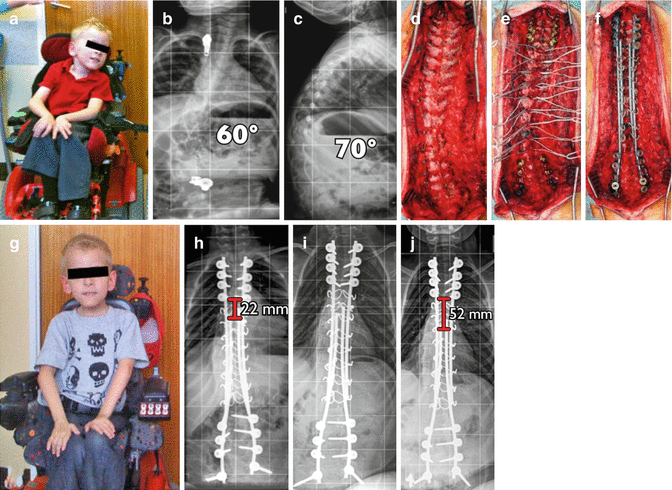
Fig. 42.2
Clinical example of a self-guided growth construct as described by Mehdian et al. treating an early onset neuromuscular scoliosis in a child with spinal muscular atrophy. (a) Preoperative clinical pictures. (b, c) Sitting AP and lateral x-rays pre-op. (d) Intraoperative pictures illustrating direction. (e) Multiple segmental sublaminar wires fixation points. (f) Intraoperative correction with four rods. (g) Postoperative clinical pictures. (h–j) Postoperative x-rays immediate, 1 year, 3 years, respectively, confirming spinal growth of 30 mm
Table 42.1
Control of spinal deformity of patients with early onset neuromuscular scoliosis treated with the self-growing rod (SGR) system
ID | Sex | Diagnosis | Complication | Age | Follow-up (years) | Preoperative scoliosis (degrees) | Final scoliosis (degrees) | Preoperative kyphosis (degrees) | Final kyphosis (degrees) |
|---|---|---|---|---|---|---|---|---|---|
1 | F | Hypotonia | None | 9 | 6 | 40 | 7 | 58 | 22 |
2 | F | SMA | Failure of fixation due to pullout from the iliac wing | 9 | 6 | 60 | 41 | 98 | 38 |
3 | F | Hypotonia | None | 9 | 5 | 92 | 8 | 76 | 31 |
4 | M | SMA | None | 9 | 5 | 78 | 38 | 71 | 32 |
5 | M | Muscular dystrophy | None | 9 | 3 | 71 | 7 | 76 | 30 |
6 | M | SMA | None | 8 | 5 | 73 | 7 | 81 | 29 |
7 | M | Muscular systrophy | None | 6 | 4 | 68 | 30 | 89 | 29 |
8 | F | SMA | None | 6 | 3 | 72 | 16 | 63 | 31 |
9 | M | Muscular dystrophy | None | 8 | 2 | 60 | 11 | 71 | 26 |
10 | F | SMA | None | 6 | 4 | 40 | 7 | 57 | 22 |
11 | M | SMA | Superficial wound infection that was treated with antibiotics | 7 | 2 | 110 | 21 | 81 | 23 |
12 | M | SMA | None | 6 | 2 | 59 | 25 | 93 | 31 |
13 | F | SMA | None | 4 | 2 | 70 | 17 | 68 | 27 |
14 | M | Muscular dystrophy | None | 8 | 2 | 72 | 20 | 74 | 29 |
15 | F | SMA | None | 7 | 2 | 77 | 23 | 76 | 27 |
Mean | 7.4 | 3.5 | 69.47 | 18.53 | 75.47 | 28.47 | |||
Table 42.2
Mean (range) of preoperative, postoperative, and final measurements of patients with early onset neuromuscular scoliosis treated with the self-growing rod (SGR) system
Preoperative | Postoperative | Final | |
|---|---|---|---|
Scoliosis | 69° (40–110°) | 16° (6–20°) | 18° (7–41°) |
Kyphosis | 75° (57–98°) | 23° (15–34°) | 28° (22–38°) |
Coronal balance | 12 cm (7.5–16 cm) | 4 cm (1–6.5 cm) | 8 cm (3.5–15 cm) |
Pelvic obliquity | 35° (28–41°) | 5° (0.3–14°) | 12° (3–21°) |
T1–S1 height | 25 cm (22–30 cm) | 32 cm (28–35 cm) | 37 cm (32–42 cm) |
T1–S1 height growth | Average yearly 1.4 cm (0.7–2.5 cm) | ||
T6–T12 ratio | 0.8 (0.7–0.9) | 0.7 (0.6–0.9) | 0.7 (0.6–0.8) |
FVC | 64 % (59–74 %) | 67 % (61–77 %) | 57 % (50–61 %) |
42.4 Surgical Technique
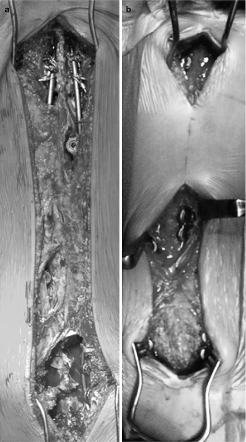
For the modern Luqué trolley, patients are positioned prone on a radiolucent table under a total intravenous general anesthetic compatible with multimodality spinal cord monitoring. Preoperative planning is mandatory to plan the skin incision as well as the location of the gliding anchors. Classic midline incisions are to be made ensuring that no prominent spinal implant will be directly below the skin incision. Either one single skin incision is made spanning the entire planed instrumented spine (Fig. 42.3a). Two or three separate skin incisions can be made over the proximal, apical, and distal segments (Fig. 42.3b). Currently, only the Shilla system has been FDA approved as gliding anchors; it has a special locking cap that does not bind to the rods. There is also a trolley-gliding vehicle that is currently only available in Europe that captures the rod with a cable tie mechanism allowing for gliding. Other implants can be used in such a fashion allowing for certain gliding properties. The oldest segmental fixation is a sublaminar wire and it can be used as a gliding anchor. The other possibility is to purposely use a smaller diameter rod (5 mm) in a pedicle screw-based system designed to capture a larger diameter rod (6 mm). For example, the pedicle screws of the AO universal spine system can be used with its small stature AOUSS 5-mm rods. Obviously, using spinal instrumentation in this way is off-label and is not recommended by any of the manufacturers. The classic modern Luqué construct consists of fixed proximal and distal anchorage points. A classic subperiosteal dissection is performed at the proximal and distal segment, as these segments need to be fused to achieve long-term solid anchors. Fixed spinal anchors such as standard screws or hooks locked to the rods are inserted. The gliding spinal anchors (either gliding screws or sublaminar wires free to travel along the rods) are inserted through muscle-sparing “keyhole” dissections (see Fig. 42.3a, b). At the apex of the deformity, gliding anchors are placed for maximal apical translation and deformity correction. The dissection at the gliding anchors must be kept to a minimum using extraperiosteal and muscle-sparing techniques to avoid spontaneous fusion. In the lumbar spine, the gliding pedicle screws are inserted through a Wiltse approach sparing the joints and minimizing bony exposure. In the thoracic spine, the gliding pedicle screws are inserted laterally to the midline erector spinae, dissecting directly onto the transverse process avoiding exposure of the lamina (Fig. 42.4a, c). Pedicle screw insertion should be done with the use of intraoperative imaging. Fluoroscopy can be used to confirm the pedicle entry point, and using a freehand technique, the gliding screws can be inserted at strategic points allowing for maximal apical translation. These gliding screws capture a 5-mm rods with a locking cap designed for 6-mm rods, thus permitting motion. At segments where sublaminar titanium cables are to be passed, the dissection is carried from midline to the medial border of the facet. Careful attention should be paid in order to leave the periosteum on the bone even with some muscle still attached. Dissection is to be performed with bipolar cautery and forceps at hand to control blood loss and minimize disruption of the periosteum. Avoid removing the spinous processes to prevent stripping the periosteum off the lamina and creating a raw bone surface. Small lateral laminectomies are to be done leaving the periosteum intact, while giving access to the ligamentum flavum. Once the central ligamentum flavum is removed, passage of sublaminar cables can be performed (Fig. 42.5). Once the fixed and gliding anchors are placed, two pairs of 5-mm titanium rods are tunneled in a subfascial/intramuscular fashion (below the fascia, above the periosteum) from the opened proximal and distal incisions. Each rod needs to only have one end rigidly anchored to the spine. In the intermediate segments, a series of gliding spinal anchors maintains the correction by keeping the rods parallel and engaged. As the spine grows, the rigidly proximally fixed rods will move away from the distally fixed rods (Fig. 42.6a). One can also only use two rods rather than four and have them fixed distally and have the spine grow off the proximal end (Fig. 42.6b). Correction of the spinal deformity is achieved with either a classic rod derotation maneuver (Fig. 42.7a) or an apical translation reduction maneuver (Fig. 42.7b) or in combination. As the rods are tunneled and partially engaged in the fixed and gliding anchors, and by rotating or translating the rods, the correction is achieved. The goal is to ensure that the four rods are parallel to each other. The number of gliding anchorage points will influence the ability to correct and maintain the deformity. If the number of the gliding anchors is kept to a minimum, the risk of spontaneous fusion is minimized. However, the risk of residual and recurrence of the spinal deformity is greater (Fig. 42.8). In contrast, if every spinal segment is instrumented then there is a lower risk of curve progression but a higher risk for growth retardation as spontaneous fusions may occur. The key is to have an adequate number of gliding anchors to translate the apex of the deformity toward midline, ensuring adequate correction and control of the spinal deformity without inducing spontaneous fusion. Different gliding constructs can be tailored to different spinal deformities (Fig. 42.9). This case illustrates the power of cantilevering a rod across the apex of a deformity. The spine was captured with fixed spinal anchors proximally (hooks and screws) and was then cantilevered across the two eggshell resections of the hemivertebra with an apical gliding screw and a set of gliding anchors distally. Follow-up radiographs confirm ongoing growth of the spine. Initially, the left rod extended below the disk of L5/S1 and now is at the level of the L5 pedicle screw. On the right side, a VEPTR 2 implant was used without the locking mechanism that allows for passive-guided growth. The gradual appearance of space within the male-female inlay of the VEPTR implants represents the spinal growth across the instrumented spinal growth.
 Anesthesia and Postoperative Management of Spinal Deformity Surgery in Growing Children
Regulatory Policies Regarding Pediatric Spinal Devices
Imaging of the Growing Spine
Orthotic Management for Early Onset Scoliosis
Growth Modulation Techniques: Titanium Clip-Screw Implant System (HemiBridge)
Single and Dual Traditional Growing Rods
Anesthesia and Postoperative Management of Spinal Deformity Surgery in Growing Children
Regulatory Policies Regarding Pediatric Spinal Devices
Imaging of the Growing Spine
Orthotic Management for Early Onset Scoliosis
Growth Modulation Techniques: Titanium Clip-Screw Implant System (HemiBridge)
Single and Dual Traditional Growing Rods


Related posts:
Anesthesia and Postoperative Management of Spinal Deformity Surgery in Growing Children
Regulatory Policies Regarding Pediatric Spinal Devices
Imaging of the Growing Spine
Orthotic Management for Early Onset Scoliosis
Growth Modulation Techniques: Titanium Clip-Screw Implant System (HemiBridge)
Single and Dual Traditional Growing Rods
Stay updated, free articles. Join our Telegram channel
Full access? Get Clinical Tree
