Fig. 49.1
PRSS instrumentation: (a) implant components; (b) surgical tools
The screw hooks are fixed on the lamina, which minimizes the risk of dislodgement of the hooks. Plate rod is placed on the convex side by way of lateral sidewise push to provide asymmetrical stress on both sides of the vertebral end plates, and a cylindrical rod is placed on the concave side and they are connected by the upper and lower connector thus the system forms a strong frame-like construct (Fig. 49.2). The middle and bottom parts of the rods are not fixed; therefore, the rods are free from the hole inside of the lower connector, which allow the rods upward on migration with the growth of the spinal column after operation. They have no distraction force during the operation; this decreases the risk of paraplegia. Bone fusion procedure is not required; essential normal spine can be obtained after removing the implants when the skeletal growth terminated [13].
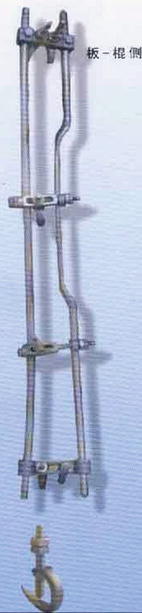
Fig. 49.2
A set of PRSS
49.3 Therapeutic Mechanism of PRSS in the Treatment of Early-Onset Scoliosis
PRSS due to its characteristics of elasticity and curve structure, and the mobility of the middle and bottom part of the instrumentation as well as absence of fusion in the operation, lacks the tether effect on the concave side of the scoliosis; this allows PRSS rod migration upward and downward during patient’s activity. In this manner, the concave side is constantly being stimulated by tensile stress, and the convex side is constantly being pushed by the lateral sidewise force, which will stimulate the growth of vertebral cartilage end plate, and at the same time it increases compression on the convex side, which inhibits the growth in this side; the subsequently asymmetrical growth over both sides of the vertebrae occurs in the subsequent growing year. Several experiments were studied which confirmed that PRSS has a function of modulating asymmetrical growth of the scoliotic spine.
The components of the PRSS system were tested with MTS machine (Material Testing System Bionex 858, Minneapolis Minnesota, USA) at the laboratory of the University of Hong Kong and Peking Union Medical College Hospital (Fig. 49.3). The results indicated higher spinal stiffness following instrumentation than those of the intact porcine spine models in vitro. Thus, bony fusion procedure is not necessary for maintaining the correction. When PRSS is implanted, asymmetrical stress is created by the lateral sideway push of the plate rod and can be calculated according to the Hooke’s law [14–16].
Fig. 49.3
Biomechanical test using porcine spine model
49.3.1 Radiographic Analysis
When PRSS is applied in the spine, asymmetrical stress is created by the lateral sideway push of the plate rod, compressive stress is exerted over the convex side, while tensile stress is exerted over the concave side of the curvature which is expressed in the form of change of the width of the disc spaces (Fig. 49.4a, b). In this manner, asymmetrical growth over both sides of the vertebral cartilaginous end plate occurs, wedging is corrected, and the vertebrae are remodeled to normal shape (Fig. 49.4a, c) [17].
Fig. 49.4
Preoperative radiograph shows disc spaces open up on the convex side and close up on the concave side all along the apical region (a), which is reversed on both side after PRSS was applied (b). Another A–P view taken 28 months after operation shows wedging vertebrae were remodeled to normal shape (compare both a and c at the arrow site), indicating asymmetrical growth on both sides
49.3.2 Photoelastic Test
Photoelastic study was used to show the mechanical properties of PRSS [18]. A model of scoliosis and correcting clamp was built on the base of similar principle (Fig. 49.5a).
Fig. 49.5
Photoelastic study shows PRSS provides asymmetrical stress on both sides of the end plates of the vertebrae: (a) A model of scoliosis and correcting clamp. (b) Photoelastic stress under different corrective loading along spine. (c, d) The asymmetrical stress data were expressed in a linear formulation of green line as change of compressive stress on the concave side; red one on convex side
According to the factual situation, the in situ stress was measured by using photoelastic and strain gage method. ANSYS (a finite element analysis software) method was also applied to simulate the experiment process and evaluate the reliability of measurement.
The results indicated that a small lateral curvature of the spine can produce asymmetrical spinal loading; the relational changes and variation of stress on both sides of scoliotic spine were demonstrated by the change on the color band in the photoelastic test. Color stripe showed more color stripe on the concave side than the convex side in the scoliotic spine (Fig. 49.5b at the top site) indicating that more compress stress in this side, and it was increased when 20 kg vertical load was given (Fig. 49.5b at the middle site); when the lateral push was applied over the convex side, more concentration of color stripe appeared on the convex side indicating compressive stress increase on this side and compressive stress decrease, and tensile stress was produced on the concave side (Fig. 49.5b at the bottom site). It was also shown that the stress value was in proportion to the correcting load. The asymmetrical stress data were expressed in a linear formulation of green line as change of compressive stress on the concave side and red one on the convex side (Fig. 49.5c, d), indicating PRSS has a significant efficiency to alter the asymmetrical mechanical loading on both sides of the scoliotic spine.
49.3.3 Type X Collagen Study
Type X collagen has also been studied to express the therapeutic mechanism. Type X collagen is used to reflect chondrogenesis, subchondral bone formation, and cartilage degeneration [19]. Type X collagen was studied as growth mark of cartilage end plate using semiquantitative RT-PCR method. The fact that more type X collagen was expressed on the convex side (Fig. 49.6-CL) than concave side (Fig. 49.6-CR) suggests that compressive stress leads to increase earlier cartilage degeneration of the convex side end plate, correlating as well with decreased growth of the end plate of this side and resulting in maximum spinal realignment.
Fig. 49.6
Type X collagen expression level
49.4 Surgical Technique
49.4.1 Surgical Procedures
The patient is placed in the prone position. A standard posterior approach and exposure as for Harrington rod procedure is made. But exposure of the subperiosteal laminae is limited to the hook sites. In this way, the unwanted spontaneous posterior ankylosis or “autofusion” is minimized.
Hook insertion: The upper and lower hooks are inserted on the lamina of the selected end vertebrae, fixed with a screw and linked with the connector (see Fig. 49.7a, b), which forms two attached points to accept the rod and plate rod. An elastic prebent plate rod is first placed on the convex side by way of the lateral sideway push. This maneuver provides asymmetrical stress on both sides of the end plate of the vertebrae all along the apical region. The lower end of this plate rod is first passed through the hole of the lower connector to an appropriate length, and free from the inside of the hole, the upper end of the plate rod is then introduced into the open head of the upper connector and fixed with the setscrew. The rod (5.5 mm in diameter) is placed on the concave side after contouring to fit the profile of the spine. This forms a frame-like spinal construct (Fig. 49.7c). The upper and the lower intermediate hooks are inserted in place in a manner similar to that of CD system. The hooks are linked with the interconnector and fastened with the rod and plate rod using the U-shaped ring. This allows additional correction of scoliotic curve. The screw caps of the intermediate screw hook on the concave side are tightened to bring the screws and its linking lamina backward for derotation of the vertebral bodies over the apical area (Fig. 49.8a, b).
Fig. 49.7
 Anesthesia and Postoperative Management of Spinal Deformity Surgery in Growing Children
Regulatory Policies Regarding Pediatric Spinal Devices
Imaging of the Growing Spine
Orthotic Management for Early Onset Scoliosis
What Can We Learn About Ribs and Vertebra Growth from an Osteological Collection?
Single and Dual Traditional Growing Rods
Anesthesia and Postoperative Management of Spinal Deformity Surgery in Growing Children
Regulatory Policies Regarding Pediatric Spinal Devices
Imaging of the Growing Spine
Orthotic Management for Early Onset Scoliosis
What Can We Learn About Ribs and Vertebra Growth from an Osteological Collection?
Single and Dual Traditional Growing Rods


Sketch map of correction of scoliosis with PRSS. (a) Screw hooks are placed under laminae and fixed onto the laminae. (b) Linked with the connector. (c) Plate rod is placed on the convex side and rod is placed on the concave side. This forms a frame-like spinal construct (Courtesy of Jin Lin)
Related posts:
Anesthesia and Postoperative Management of Spinal Deformity Surgery in Growing Children
Regulatory Policies Regarding Pediatric Spinal Devices
Imaging of the Growing Spine
Orthotic Management for Early Onset Scoliosis
What Can We Learn About Ribs and Vertebra Growth from an Osteological Collection?
Single and Dual Traditional Growing Rods
Stay updated, free articles. Join our Telegram channel
Full access? Get Clinical Tree
