Fig. 47.1
MAGEC System: (a) MAGEC rods (1) standard and (2) offset (b) MAGEC Manual Distractor (MMD) (c) Magnet Locator (MML) and (d) External Remote Controller (ERC model 1) (Courtesy of Behrooz A. Akbarnia, MD)
In this chapter, we will focus on the indications, surgical technique, and early results of this procedure and compare the clinical outcomes of the MCGR and TGR techniques for the treatment of EOS.
47.3 Indications
The device has FDA clearance for the treatment of progressive EOS in immature patients with or at risk of thoracic insufficiency syndrome (TIS).
47.4 Contraindications
Patients with infections or pathologic conditions of the bone which could impair the ability to securely fix the device (e.g., osteoporosis, osteopenia)
Patients with metal allergies and sensitivities to the implant materials (e.g., titanium).
Patient with a pacemaker or other active, electronic devices (e.g., implantable cardioverter defibrillator)
Patient requiring MR imaging during the expected period of device implantation
Patients younger than 2 years old
Patients weighing less than 25 lbs (11.4 kg)
Patients and/or families unwilling or incapable of following postoperative care instructions
Patients with stainless steel wires or other implants containing incompatible materials
47.5 Surgical Technique
The technical principles of this procedure are similar to those of traditional growing rod (TGR) described elsewhere in this book. Following the proper patient positioning and preparation of the surgical site, the selected levels of foundations are approached through one or two midline incisions, and anchors are implanted using screws, hooks, bands, or a combination, per patient’s needs and the surgeon’s choice over two or more levels if needed. Usually, hooks and/or pedicle screws are used as proximal anchors and screws for the distal foundation. The selection of the levels and preparation of the foundations is similar to that of TGR [6] (see Chap. 38).
47.5.1 Rod Preparation and Contouring
A template (e.g., a typical anesthesia stylet) can be used to determine the length of the rod with consideration of extra length based on anticipated intraoperative correction and distraction. Preoperative flexibility radiographs can help in planning the location of the actuator, size, and length of the rods. The concave rod is usually prepared first. It is cut and contoured to fit the desired sagittal alignment. Some surgeons apply a temporary convex rod first to maintain the distraction and more accurately estimate the rod length. Care should be taken to avoid any bending of the actuator or within 20 mm of it. For extensive contouring or for smaller stature children, the 70 mm actuator may be an alternative to provide more rod length available for bending.
47.5.2 Rod Testing
It is very important to verify that the rod distracts correctly after contouring and prior to implantation. The MAGEC® Manual Distractor (MMD) will self-align over the zone marked “MAGNET.” Mark the rod where it first exits the actuator with a sterile marker to aid in visualizing movement of the rod. Next, slide the MMD over the implant zone marked with the letters “MAGNET” while maintaining standard sterile technique. Rotate the MMD by hand about the centerline axis of the actuator counterclockwise when viewed from the distal end of the implant with the arrow pointed up (cephalad). This will cause the implant to distract (lengthen) (Fig. 47.2). It is recommended that four full counterclockwise rotations are performed to ensure the rod is properly functioning. After confirmation, three full clockwise rotations should be done to return the rod almost to its neutral position and avoid jamming.


Fig. 47.2
Distraction and testing by MMD. Note the counterclockwise direction of the MMD (Courtesy of Behrooz A. Akbarnia, MD)
47.5.3 Rod Orientation
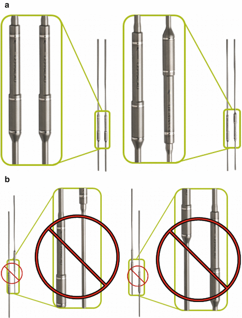
When using dual rods, a combination of two single standard rods or a single standard rod and an offset rod combination can be used. Standard rods may be chosen if the surgeon’s preference is to distract the rods at the same time in the same direction. A standard and an offset rod combination may be chosen if the surgeon’s preference is to distract the rods individually and in opposite directions since the magnets are located at opposite ends of the actuator portion. Regardless of the type of the rod, it has been suggested that they are placed with the actuators at the same level for the best function (Fig. 47.3). Anatomically, the best location for the rods is the thoracolumbar junction, but it could be placed in other levels with consideration of sagittal alignment.


Fig. 47.3
Implant location in dual-rod technique: actuators are placed at the same level for the best function. Note (a) correct and (b) incorrect positions (Courtesy of Ellipse Technologies, Inc.)
47.5.4 Rod Insertion
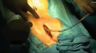
A standard chest tube may be used to tunnel the rod subfascially between the two foundations. Then, preliminarily attach the rods to the anchor sites at first proximally and then distally. Insert the concave rod first for single curves. Tunneling the rod can be assisted by first passing a chest tube subfascially and then use the same tunnel for passing the rod or using a long clamp (Fig. 47.4). The second rod is then cut, contoured, and passed in the same manner. Some surgeons prefer to use a temporary rod on the convex side and then use the permanent rod on the concave side for more accurate rod measurement. Both rods are then attached to the upper foundation first making sure that they are in proper sagittal orientation. The entire upper foundation anchors are preliminarily tightened, and a cross-connector is attached between two rods if needed to complete the upper foundation construct. The lower foundation is then constructed, where both rods are attached to the lower anchors loosely and the concave rod followed by the convex rod is distracted. No cross-link is applied distally unless hook anchors are used. After radiographic check, the wounds are irrigated, foundations are prepared for fusion, bone graft is placed, and wounds are closed.


Fig. 47.4
Passing the rod subfascial: the rod is being introduced using a chest tube (Courtesy of Behrooz A. Akbarnia, MD)
47.6 Lengthenings
47.6.1 Method of Lengthening
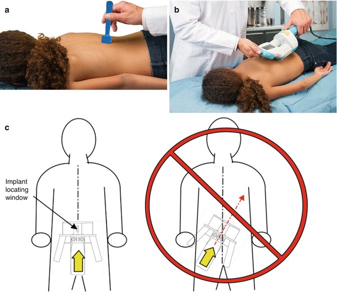
There are two methods of distraction, incremental mode and continuous mode. The External Remote Controller (ERC) contains two large magnets that are rotated when the ERC is activated. The magnets of the ERC couple to the magnet in implanted actuator portion of the rod. When the ERC magnets rotate, the coupling causes the implanted magnet to rotate, and the implanted rod to change in length. If the first method of distraction is selected, the ERC is placed in the “incremental” mode and the desired distraction amount is entered in the control panel. The patient is placed in the prone position on the examining table. The MAGEC Magnet Locator (MML) is held vertically near the distal end of the device at the location of the actuator (Fig. 47.5a, b). It is place just above the skin surface of the patient that approximates the location of the internal magnet and allows the locator to be pulled to the strongest point of attraction. The locator will naturally attract itself to the internal magnet. Mark the point on the skin and position the implant-locating window of the ERC over the magnet area that is marked. The ERC should be oriented along the axis of the implant with its orientation arrow pointing towards the patient’s head (Fig. 47.5c). Lastly the “on” button is pushed and the device is lengthened as the ERC is activated. Since the amount of the lengthening has already been entered, the ERC will stop when the distraction is complete.


Fig. 47.5
Lengthening: (a) MML skin placement on the site of magnet. (b) ERC 2 was used for distraction. (c) Correct placement of ERC in relation to the magnet (a, b: Courtesy of Behrooz A. Akbarnia, MD; c: Courtesy of Ellipse Technologies, Inc.)
Alternatively, continuous mode can be used for distraction. The ERC is placed in continuous mode, and distraction is done as the previous method until the device stalls. Distraction is then stopped. This indicates that the maximum distraction force of the implant has been reached.
47.6.2 Frequency of Lengthenings
The lengthenings in MCGR can be accomplished more frequently than in TGR since MCGR distractions are noninvasive and lengthening can be performed in the clinic. The ideal interval is not yet known, but finite element analysis (FEA) studies have suggested that more frequent lengthenings may put less stress on the rod and possibly reduce rod fractures [7]. Cheung et al. in a study of 30 patients with minimum of 2 years follow-up has also shown that more frequent lengthenings (1 week to 2 months) is associated with less implant complications but increased incidence of proximal junctional kyphosis and difficulty in lengthening compared to less frequent lengthenings (3 months and longer) [8].
Stay updated, free articles. Join our Telegram channel

Full access? Get Clinical Tree


