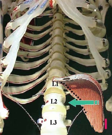
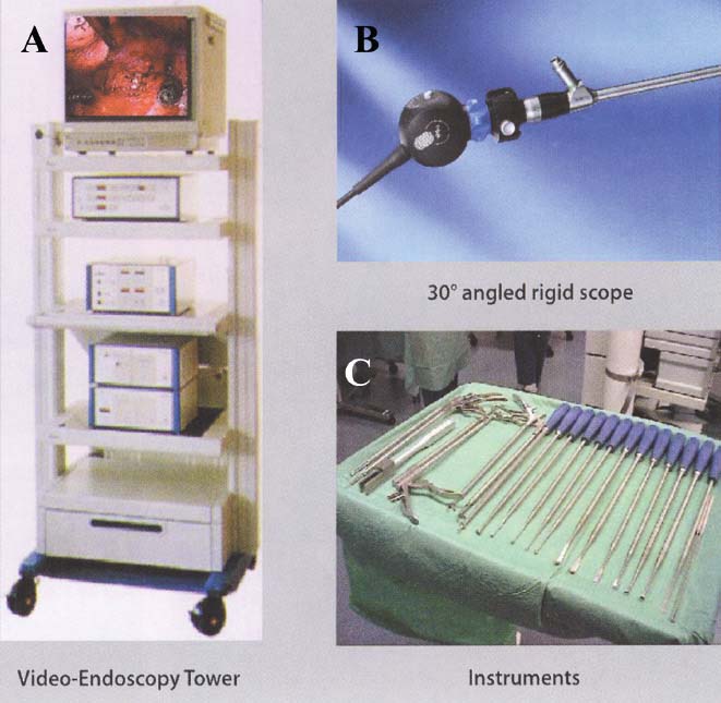
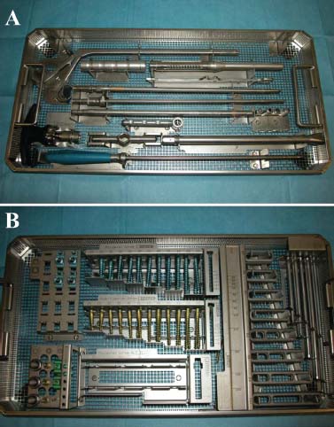
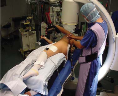
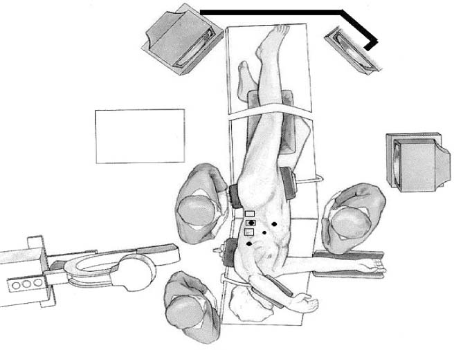
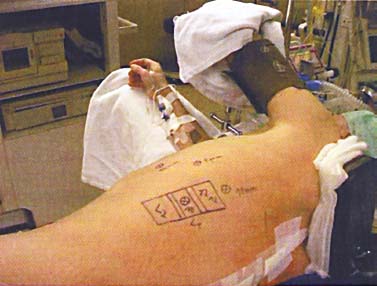
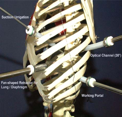
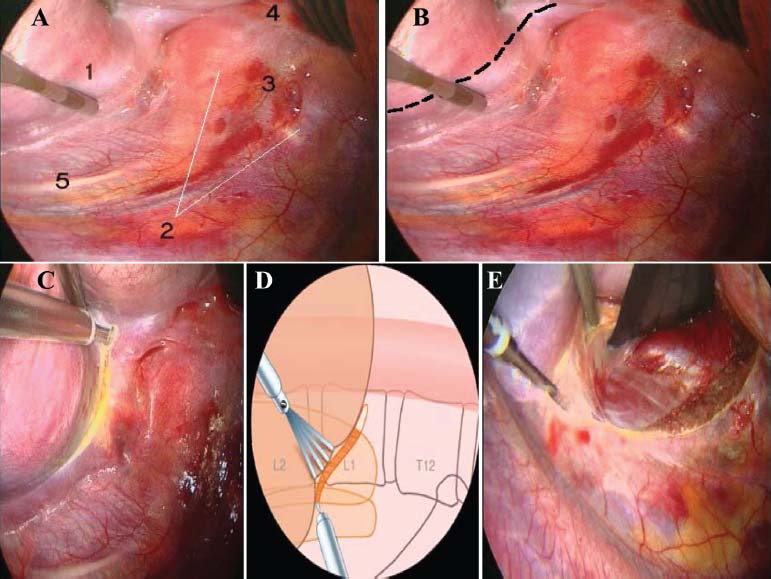
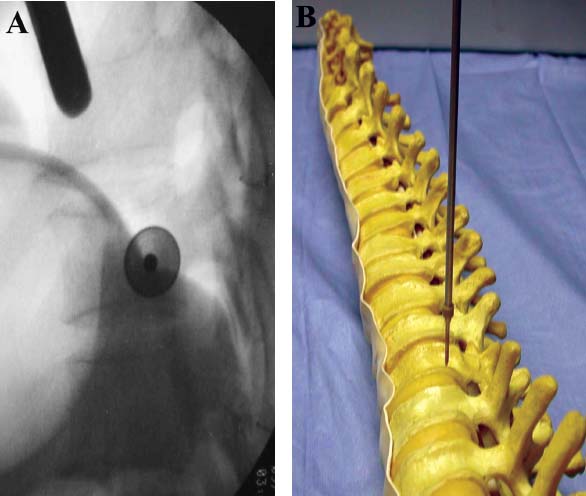
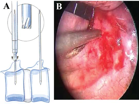
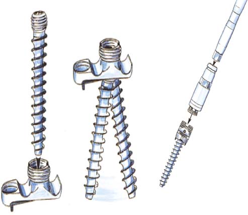
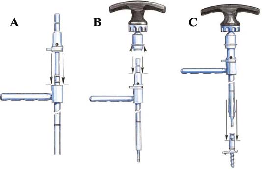
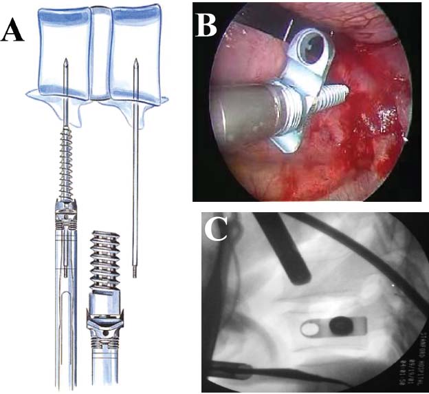
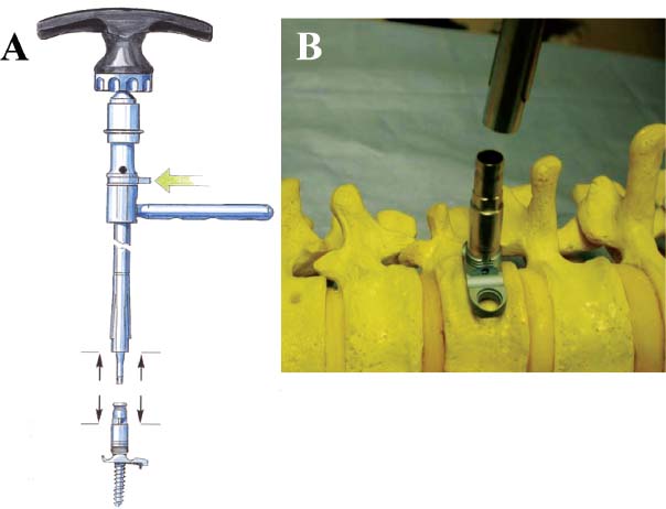
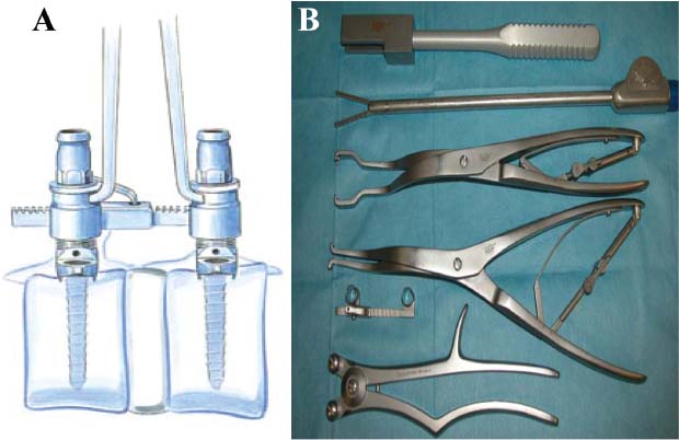
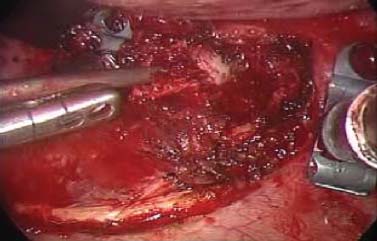
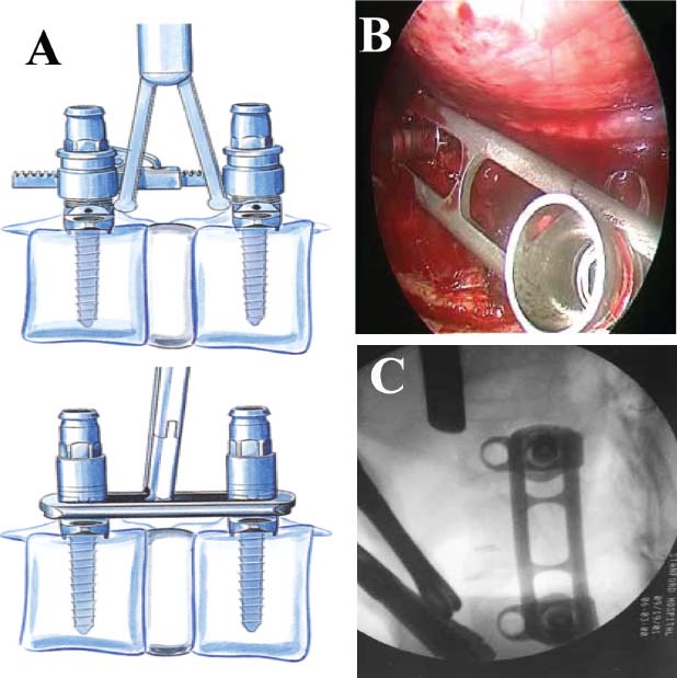
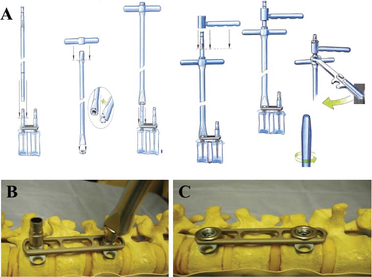
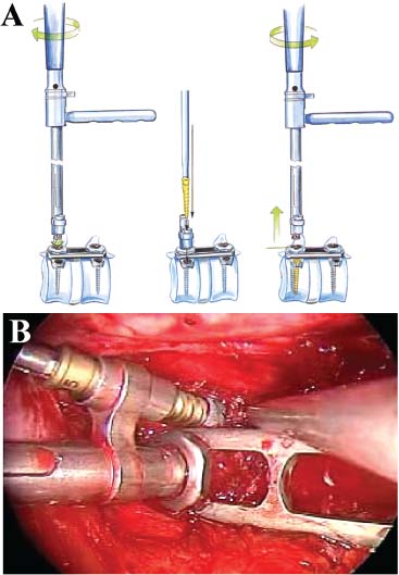
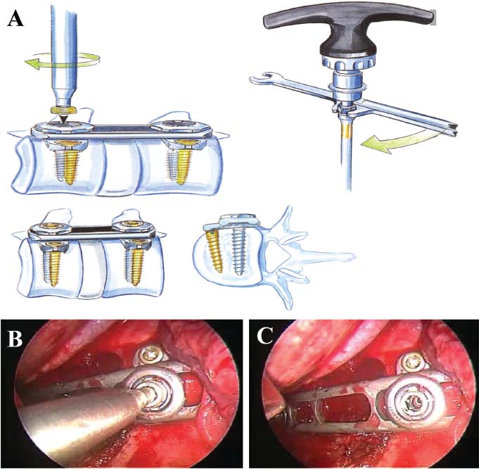
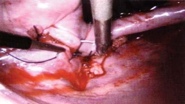
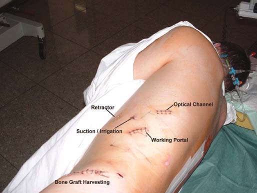
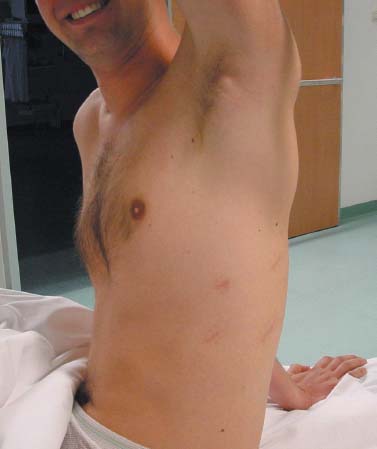
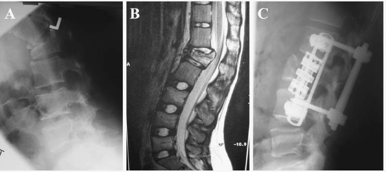
Thoracoscopic techniques have long been used by thoracic surgeons, who have had excellent experience and good results over the last decade. For spine surgeons, it represents a new procedure for treating spine problems through an anterior approach. The anterior approach in spine surgery has long been accepted for corpectomy, decompression, and stabilization. Unfortunately, a thoracotomy or thoracoabdominal approach is marked by high morbidity, with frequently occurring pain syndromes, relaxation of the abdominal wall, or neuralgia of the posterior segment nerves. Because the most common location of the thoracic spine fractures involve the thoracolumbar junction, this morbidity is again increased by the required diaphragm detachment. The attempt to incorporate biomechanical advantages by using an anterior approach and to avoid the disadvantages of high morbidity by means of minimally invasive techniques has been addressed by various authors. It has expanded its application from metastatic spine disease and degenerative diseases to thoracolumbar spine trauma and deformity correction from any causes. The anatomically performed thoracic cavity allowed thoracoscopic access to the thoracic vertebrae T4-T12 without any major preparatory work. Even the rostral lumbar spine can be safely reached thoracoscopically by detaching the diaphragm. At the level of the second or third lumbar vertebra, further diaphragm detachment and proper retraction make it possible to expose the entire thoracolumbar transition for minimally invasive endoscopic procedures. This is made possible by an anatomical peculiarity of the pleural cavity and the diaphragmatic insertion, the lowest portion of which (i.e., the costodiaphragmatic recess) is projected onto the spine with perpendicular projection just on the base plate of the second vertebra (Fig. 17–1). Thus, the thoracic spine, as well as upper lumbar spine from T4 to L3, is accessible endoscopically using the thoracoscopic technique. The goals of thoracoscopic surgery include neural decompression, restoration of normal curvature, and stability of the affected motion segment(s). This is usually achieved in a two-step procedure that includes posterior reduction and stabilization with a pedicle screw system if necessary in patients with significant deformity or three-column involvement. Anterior decompression of the spinal canal, reconstruction of the vertebra, and interbody fusion with autogenous bone graft (or bone-impacted cage) and screw plate fixation are performed through a thoracoscopic anterior approach, which can be extended into the retroperitoneal space down to L3 with thoracoscopic diaphragm detachments, if necessary. Indications As an alternative approach to thoracotomy or thoracoabdominal approach, the thoracoscopic technique can be used to perform thoracic corpectomy to decompress the spinal canal and to reconstruct and fixate the segments affected by destructive disease and trauma. The anterior thoracoscopic approach is indicated in the following situations (in combination with posterior instrumentation if needed): FIGURE 17–1 Extent of diaphragmatic opening by the thoracoscopic approach along the spine and ribs is marked for exposure of L2 vertebra. Note that the lowest point of the diaphragmatic insertion [i.e., the costodiaphragmatic recess (arrow)] projects onto the spine perpendicularly just above the base plate of L2. Thus, a minimal diaphragmatic opening (6–10 cm) allows instrumentation of L2 vertebra. Contraindications The thoracoscopic approach is contraindicated in the following situations: Instruments The following instruments are necessary to perform endoscopic-assisted anterior approaches to the thoracic and lumbar spine: Anesthesia The procedure is performed with the patient under general anesthesia. Selected intubation with onelung ventilation facilitates intrathoracic preparation. The positioning of the double-lumen tube is controlled by a bronchoscopic technique. A Foley catheter is placed, as well as central venous lines and an arterial line for continuous blood pressure monitoring. FIGURE 17–2 (A) Video-endoscopy tower with light source, monitor, and control station. (B) Right 30-degree-angled endoscope. (C) Thoracoscopic instruments set with varying sizes of osteotomes, curettes, rongeurs, and graspers. Positioning The patient is placed in a stable lateral position on the right side and fixed with a four-point support at the symphysis, sacrum, and scapula, as well as with arm rests (Fig. 17–4). A left-sided position is preferred for the treatment of fractures from T4 to T8. A right-sided position is preferred for the approach to the thoracolumbar junction (T9–L3). Care has to be taken that the upper arm is abducted and elevated in order not to disturb the placement and manipulation of the endoscope. Before the operation starts, the position and free tilt of the C-arm must be checked. Sterile draping extends from the middle of the sternum anterior to the spinous processes posterior, as well as from the axilla down to ~8 cm caudal to the iliac crest. Both monitors should be placed at the lower end of the operating table on opposite sides to enable free vision for the surgeon and the assistant. The operating room setup is shown in Figure. 17–5. The surgeon and the camera operator stand behind the patient. The C-arm approach is between the surgeon and the camera operator. The assistant and the C-arm monitor are placed on the opposite side. Surgical Technique The surgical technique of thoracoscopic spine surgery has been described in detail by various authors.2–4 Early on in our experience, we often reserved the thoracoscopic approach for thoracic fractures involving the T4 to T10 vertebrae. With increasing experience, we extended the indications to pathologies involving the thoracolumbar junction. FIGURE 17–3 (A,B) MACS-TL (modular anterior construct system for thoracolumbar spine) instrumentation set. FIGURE 17–4 Operative photograph showing lateral positioning (on the right side) of the patient on a Jackson table. Localization The target area (e.g., Ll fracture) is projected onto the skin level under fluoroscopic control (Fig. 17–6). The borders of the fractured vertebra are then marked on the skin. The working channel is centered over the target vertebra (12.5 mm). The optical channel (10 mm) is placed two or three intercostal spaces cranial to the target vertebra in the spinal axis. For fractures of the middle and upper thoracic spine, the optical channel is placed caudal to the target vertebra. The approach for suction/irrigation (5 mm) and retractor (10 mm) is placed ~5 to 10 cm anterior to the working and optical channel. Placement of Portals The position of the portals in relation to one another and to the operating site on the spine influences the entire course of the operation. The injured spinal section is therefore first projected exactly orthograde onto the lateral chest or abdominal wall using an image intensifier, then drawn onto the skin with a marker pen, indicating the line of the anterior and posterior edges as well as the end plates of the affected segments. The operating portal is the first position to be marked exactly over the target area; corresponding to this, the portal for the optical channel is drawn in over the spine, two or three intercostal spaces above the mark for the operating portal for thoracolumbar access, or underneath it for access to the central or upper thoracic spine (Figs. 17–7, 17–8). The portal for the suction and irrigation instrument is about four fingerbreadths from the operating portal in a ventral and cranial direction. The portal for the diaphragm or lung retractor should be placed as far as possible ventrally to avoid instruments coming into conflict. It is sometimes helpful to make two separate working portals, which are directed onto the vertebra to be fixed (above and below the affected segment). The operation is started with the most cranial approach (optical channel). Small Langenbeck hooks are inserted through a 1.5 cm skin incision above the intercostal space. The muscles of the thoracic wall are crossed in a blunt, muscle-splitting technique, and the intercostal space is opened by blunt dissection, thus exposing the pleura and creating an opening to enter the thoracic cavity, A 10 mm trocar is inserted, and one-lung ventilation is started. A 30-degree endoscope is inserted at a flat angle in the direction of the second trocar. Perforation of the thoracic wall to insert the second, third, and fourth trocars is performed under visual control through the scope, and the other trocars are inserted as shown. FIGURE 17–5 Operating room setup for thoracoscopic spine surgery. Note that the surgeon and the assistant holding the camera stand behind the patient, with the video and fluoroscopic monitor in front of them. FIGURE 17–6 Localization. The target vertebra is projected and marked on the skin and marked under a fluoroscopic table. Prevertebral Dissection and Diaphragm Detachment The target area can now be exposed with the help of a fan retractor inserted through the anterior port. The retractor holds down the diaphragm and exposes the insertion of the diaphragm on the spine. Compared with extensive thoracolumbar exposures with total detachment of the diaphragm required for open surgery, the thoracoscopic approach to the thoracolumbar junction allows minimal diaphragmatic detachment. Thus, with a diaphragmatic opening of ~6 to 10 cm, the entire L2 vertebral body can be exposed (Fig. 17–9). First, palpate the anterior circumference of the motion segment and the course of the aorta with a blunt probe. “Mark” the line of dissection for the diaphragm with monopolar cauterization. Next, incise the diaphragm using endoscissors. A rim of 1 cm should be left on the spine to facilitate closure of the diaphragm at the end of the procedure. The preferred incision runs along the spine and the ribs parallel to the diaphragmatic insertion and 1 to 2 cm away from it. The diaphragm is already thinner here than it is in the immediate area of insertion, and the remaining edge makes subsequent suturing easier. Retroperitoneal fat tissue is now exposed and mobilized from the anterior surface of the psoas insertions. Carefully dissect the psoas muscle from the vertebral bodies in order not to damage the segmental blood vessels “hidden” underneath (Fig. 17–9). The retractor can now be placed into the diaphragmatic gap. FIGURE 17–7 Diagram showing the placement for thoracoscopic portals for approaching the thoracolumbar junction. FIGURE 17–8 Skeletal model showing the placement of portals for thoracoscopy. The thoracoscope (10 mm) is placed two or three intercostal spaces cranial to the target vertebra. The working channel is placed over the target vertebra. Portals for suction/irrigation (5 mm) and retractor (10 mm) are placed ~5 to 10 cm anterior and cranial to the working portal. Screw Insertion Preparation Insert a self-tapping screw under fluoroscopic control in the vertebra superior to the fractured one, as well as in the fractured vertebra. Next, insert the first screw of the MACS-TL system (Aesculap, Melsungen, Germany) into the caudal vertebral body. Open the cortical surface with a sharp trephine ~1 to 1.5 cm from the posterior border of the vertebral body infra- and supradjacent to the fracture. K-Wire Insertion Next, insert the K-wire in the distal cannulated end of the instrument, and connect it with the K-wire impactor. Position the K-wire under fluoroscopic control (Fig. 17–10). The patient must be placed in a lateral position to expose the posterior edge of the corresponding vertebral body. It is important to confirm the perpendicular position of the patient to the beam. If the instrument charged with the K-wire is well aligned, a dark inner point and a concentric ring will be observed, and the correct placement is ensured. If a line is observed on x-ray, the K-wire is not positioned parallel. Following alignment, the K-wire is impacted until it is stopped by the gray ring of the instrument (20 mm). For safe screw implantation, the K-wire should be inserted ~10 mm away from the posterior edge of the vertebral body and 10 mm away from the end plate. Afterwards, release the K-wire by turning the knob of the impactor counterclockwise. The complete instrument can then be pulled back, with the K-wire remaining in place. Decortication A cannulated punch is used for a slight removal of cortical bone to prepare the entry hole for the polyaxial screw (Fig. 17–11). Centralizer Attachment The twin screws and the polyaxial clamp have to be preassembled before insertion. The centralizer has to be attached either to the polyaxial plate or to the twin screws. It then has to be screwed into the inner thread. This is accomplished by using the hex key for the centralizer. For rotational locking, the centralizer has two flanges, which correspond to the slots of the clamp. When fully seated, the centralizer should be snug but not overtightened (Fig. 17–12) Assembly of Insertion Instrument The handle must be connected to the proximal end, the external hex, of the insertion sleeve. The cannulated screwdriver has to be positioned through the insertion sleeve until it locks in position. The ratchet handle is connected to the cannulated screwdriver, and the ring of the Harris connector has to be pushed proximally. The assembled insertion instrument is then connected to the hexagonal end of the centralizer. The spring of the insertion sleeve snaps into the corresponding groove of the centralizer. The orientation of the polyaxial plate should correspond to the direction of the handle to ease the orientation, especially in endoscopic procedures. The polyaxial screw is put into a straight direction to attach the screwdriver (Fig. 17–13). Screw Insertion Next, place the polyaxial, posterior screw over the K-wire. The direction of the polyaxial clamp can be controlled by the handle. The clamp has to be oriented so that the hole for the anterior stabilization screw comes to lie anteriorly. After the initial turns of the screw into the vertebral body, the K-wire has to be removed to avoid the risk of tissue perforation by pushing the K-wire forward during screw insertion (Fig. 17–14) FIGURE 17–11 (A) Decortication to prepare for entry hole for the polyaxial screw. (B) Thoracoscopic view showing the decortication of the entry hole. FIGURE 17–12 Centralizer attachment. FIGURE 17–13 (A–C) Diagram showing the steps in the assembly of the insertion instrument. K-Wire Removal After partial insertion of the polyaxial screws, the K-wire has to be removed. Insert the removal instrument through the insertion instrument, and attach it to the K-wire by turning the removal instrument clockwise and screwing it onto the wire. The K-wire can then be pulled out through the cannulated instrument. Insertion Instrument Removal Push the slide of the insertion instrument, then release the instrument from the centralizer by pulling backward. The segmental vessels of the fractured vertebra are then mobilized, closed with vascular clips, and dissected (Fig. 17–15). Distraction Maneuvers After diskectomy or vertebrectomy and proper preparation of the graft bed, distraction can be applied to the vertebral bodies to insert a graft that is slightly larger than the prepared disk space and to achieve graft compression. Place the distraction ratchet (Fig. 17–16) over the centralizers using holding forceps. According to the distance between the centralizers, choose the appropriate distraction bar. Before placing the ratchet onto the centralizers, unlock the bolt to allow the instrument to slide and be adjusted to the proper distance. After placing the distraction ratchets on the centralizers, engage the distraction forceps between the ratchet sleeves. Before applying the distraction forceps, lock the bolt. Corpectomy and Decompression of the Spinal Canal The extent of the planned partial vertebrectomy is defined with an osteotome. First, open the disk spaces to define the borders. After resecting the intervertebral disk(s), carefully remove the fragmented parts of the vertebra with rongeurs. Radical removal of nonfractured parts of the vertebral body should be avoided. Resection close to the spinal canal is facilitated with the use of high-speed burrs. If decompression of the spinal canal is necessary, the lower border of the pedicle should first be identified with a blunt hook. The base of the pedicle should then be resected in a cranial direction with a Kerrison rongeur, and the thecal sac can be identified. Finally, the posterior fragment that occupies the spinal canal can be removed (Fig. 17–17).2,3 FIGURE 17–16 (A) Drawing showing the distraction maneuver using a distraction ratchet. (B) Various compression and distraction instrumentation and plate/rod benders used for MACS-TL instrumentation. Bone Grafting/Cage Placement Preparation of the graft bed is then completed, and the length and depth of the bone graft can be measured with a caliper. First, a tricortical bone is taken from the iliac crest. If the bone graft is longer than 2 cm, the iliac crest should be reconstructed. The bone graft should be prepared for insertion and mounted on a graft holder. The cortical bone is perforated with several burr holes to facilitate vascular ingrowth and new bone formation. Next, the working portal is removed, and a speculum is inserted. This allows the insertion of a bone graft up to 1.5 cm in length into the thoracic cavity. If the bone graft is longer, it is inserted without the use of a speculum, but with the help of Langenbeck hooks. In this case, the bone graft is mounted on the graft holder inside the thoracic cavity. Finally, insert the bone graft by press-fitting it into the graft bed. If slight reduction maneuvers are necessary, this can be achieved by manual pressure on the spinous processes of the involved segment, thus creating a segmental lordosis. FIGURE 17–17 Thoracoscopic view showing corpectomy and decompression of the spinal canal. Plate/Rod Placement The distance between the polyaxial heads has to be measured. If plates are used, 30 mm must be added to select the proper plate length. The stabilization plate is then placed over the centralizer onto the polyaxial heads. The rounded side with the markings is on the upper side of the plate. In cases of multisegmental assemblies, rod connection has to be chosen. Both rods have to be contoured in the same fashion. The anterior border of the polyaxial plate is slightly lower than the posterior. Thus, the posterior rod can be placed and temporarily closed by slightly tightening the nut to avoid rod loosening. A placement of the anterior rod is now still possible. For both types of clamp, a degree of freedom should be preserved to allow angulation of the polyaxial heads. Final screw insertion is performed after the plates are placed and tightened with the fixation nuts (Fig. 17–18). FIGURE 17–18 Plate/rod placement shown in diagram (A), thoracoscopy surgery (B), and plain radiograph (C). Final Fixation Next, the insertion sleeve is attached on the centralizer. After the plate or rod is placed and the polyaxial plate is well aligned, the assembly can be closed by using a fixation nut. The nut should be placed with the smooth part against the stabilization plate. Using the cannulated nut driver, the nut can be placed over the centralizer. To apply countertorque during the tightening process of the nut, attach the handle to the insertion sleeve. Prefixation can be achieved using the nut driver with the countertorque handle. For final fixation, the torque wrench is applied to the nut driver, and countertorque is again applied by using the handle on the insertion sleeve. Thus, no torque is applied to the spine (Fig. 17–19). Removal of the Centralizer To remove the centralizer, attach the insertion sleeve with the handle and hex key to the centralizer. Remove the centralizer from the polyaxial clamp by turning the screwdriver counterclockwise (Fig. 17–20A). Tightening of the Polyaxial Screws Next, the assembly must be brought into final position directly onto the surface of the vertebral bodies. To achieve this, insert the screws until the plate is in direct contact with the bone (Fig. 17–20B). Insertion of the Anterior Screw The screw-guiding sleeve for the anterior stabilization screw has to be attached to the polyaxial clamp. To do so, insert the insertion sleeve with the handle and the hex key for the centralizer to the hexagonal end of the guiding instrument (same mechanism as for the centralizer). With the central punch, the cortex is then penetrated. After selecting the appropriate screw length, fix the anterior screw to the screwdriver with a retaining clip, then insert it through the guiding instrument into the vertebral body (Fig. 17–21). The guiding instrument can then be removed (same mechanism as removal of the centralizer). FIGURE 17–19 Illustrative diagrams (A) showing the final fixation of the polyaxial screw. Bone model (B,C) showing the final fixation of the screw. FIGURE 17–20 Diagram showing centralizer removal (A) and tightening (B) of the polyaxial screws. Insertion of Locking Screws To lock the polyaxial mechanism, attach the yellow locking screw to the screwdriver with a retaining clip. The instrument has to be positioned perpendicular to the plate/rod. Tighten the locking screw with a torque of 10 nm (Fig. 17–22). The torque wrench is applied to the screwdriver. Closure The retractor should be rearranged and the gap in the diaphragm closed with staples or adaptive sutures using the endoscopic technique (Fig. 17–23). Irrigate the thoracic cavity, remove any blood clots, and insert a chest tube with the end placed in the costodiaphragmatic recess. The portals can be closed with sutures after removal of the trocars (Fig. 17–24). FIGURE 17–21 Diagram (A) and thoracoscopic view (B) showing insertion of the anterior screw. Postoperative Care The patient is extubated immediately after the operation. Anteroposterior and lateral x-rays of the target area are performed postoperatively. In patients with chronic obstructive pulmonary disease, elderly patients, and patients with cardiovascular disease, artificial ventilation may be necessary for the first 24 hours after the operation. Low-dose, low-molecular-weight heparin is given for thromboembolic prophylaxis. The patient stays in the intensive care unit for 24 hours. Chest tubes can usually be removed on the first postoperative day. Mobilization and ventilation training start on the first postoperative day. Physiotherapy is started (1 hour/day) on the second postoperative day. From the third postoperative week, physiotherapy is intensified to 2 to 3 hours daily. Plain x-ray is obtained on the second postoperative day, after 9 weeks, as well as after 6 and 12 months. The patient is allowed to return to work after 12 to 16 weeks. Results The rate of conversion to the open procedure is less than 1% in our series of more than 400 cases. The average operating time of 2.5 to 3 hours, which can now be achieved for ventral treatment of fresh injuries, almost equals that for dorsal stabilization with transpedicular fusion and fixation. The average blood loss of 250 to 450 ml from the ventral endoscopic operation is less than that of a dorsal procedure. We observed a fusion of 90% with the MACS-TL system at 1-year radiological follow-up. The essential advantages of the minimally invasive surgery on the spine include the reduction of postoperative pain, the related earlier recovery of function, and the reduction in duration and intensity of painkiller administered. The aesthetic and cosmetic results (Fig. 17–25) also speak in favor of the minimally invasive procedure, reducing the emotional damage caused among the predominantly young patient group by minimizing distressing scar formation. The impression that postoperative morbidity, as well as rehabilitation time, could be shortened by the endoscopic approach was shown in a clinical study comparing the results of 30 patients, following either open or endoscopic treatment. In the endoscopic group, the duration of application of analgesics was decreased by 31%, and the overall dosage of applied analgesics was decreased by 42%.2 These results are supported by comparing our own results with those published by Faciszewski et al.5 In this multicenter study4 the complication rate of a total of 1223 open anterior approaches to the thoracic and lumbar spine were reported. The postoperative rate of pleural effusion, intercostal neuralgia, and pneumothorax was 14%, compared with 5.4% in our own series. The infection rate in the study was 0.57%, compared with 0.53% in ours. Complications The thoracoscopic procedure for corpectomy and instrumentation is relatively new, but the spectrum of complications is similar to that of open thoracotomy or thoracoabdominal approaches. The overall complication rate of the thoracoscopic technique is similar to or even less than the rate associated with postoperative functional recovery. In our series of more than 400 cases covering 5 years, such access-related complications as pleural effusion, pneumothorax, and intercostal neuralgia occurred in 5.4%. No hernia or relaxation of the diaphragm has been recorded. One transient injury of the L1 root occurred during thoracoscopic detachment of the diaphragm. FIGURE 17–22 Diagrams (A) and thoracoscopic views (B,C) showing the insertion of locking screws. FIGURE 17–23 Thoracoscopic view showing repair of the diaphragm with adaptive sutures. Injuries to major organs (lung or heart), the aorta, and vena cava are the most hazardous intraoperative complications. Distorted spine anatomy and insufficient preparation of the segmental vessels can result in accidental injury, bleeding, and loss of visual control. Other complications (e.g., dural tear, peritoneum opening, lung injury, and nerve injury by uncontrolled monopolar coagulation) can occur. Possible intraoperative complications are hemothorax, recurrent pleural effusion, intrathoracic adhesion, deep wound infection, and implant failure. Most of these complications occurred early in a series as a result of technical difficulties. With the use of the more endoscopically friendly MACS-TL implant, the complication rate has decreased gradually. Implant failure has been very rare in our experience since introducing the MACS-TL system, which is suitable for endoscopic use and provides highly stable fixation. Implant loosening was caused in two patients by advanced osteoporosis. As the analysis of plain x-ray and CT images showed, the assembly of individual components held and did not alter over time, but the entire implant assembly shifted its position in vertebral bodies. Thus, if osteoporosis is suspected, extensive dorsal and shorter ventral fixation should be considered. FIGURE 17–24 Closure of portal sites following thoracoscopic surgery and iliac bone graft harvesting. FIGURE 17–25 Postoperative scars following thoracoscopic surgery after 6 months, with excellent cosmetic result. Some of these complications require thoracotomy or open revision, which abolishes all the advantages of minimally invasive procedures. In our series, four patients needed conversion to open surgery. This was necessary in two of the first five cases, in one case due to bleeding, and in the other due to technical difficulty. The third conversion was made due to leakage from the aorta. The fourth conversion was made due to upper thoracic injury. Thus, careful preoperative evaluation and meticulous manipulation are essential to prevent disastrous complications. Technical Tips To get desirable results with thoracoscopic surgery, every step should be done carefully to avoid complications. First of all, correct positioning of the patient and the C-arm is essential. Incorrect positioning of the patient or the C-arm may result in misplacement of the screws. Even current fluoronavigation systems may not help to avoid this problem when the correct position is not established properly. Selection of working portals upon correct positioning is also critical to insert screws correctly and to prevent instrument conflicts. Insufficient preparation of the segmental vessels can result in accidental injury, bleeding, and loss by uncontrolled monopolar coagulation. Thus, the use of monopolar cauterization should be cautious near segmental arteries as well as nerve roots. Insufficient preparation of the graft bed may lead to forceful impaction, with the risk of indirect injury to the dura and spinal nerves due to displacement of bone or disk fragments into the spinal canal or foramen. To prevent these complications, meticulous dissection with proper bleeding control is mandatory. Future Developments Current minimally invasive thoracoscopic spine surgery has been developed with improvement of endoscopic techniques and instrumentation. Future development of this procedure can be enhanced with the help of an image-guided system (IGS) and a surgical robotic arm. CT and MRI-based navigation has several limitations, but fluoroscopic navigation can provide near-real-time imaging. The authors’ initial experience using an IGS was impressive, especially in cases involving tumor deformity or trauma. This combination technique is also helpful in driving the screws for short-segment combined (anterior and posterior) fixation. Another potential possibility to improve the effectiveness of the thoracoscopic procedure is to utilize a surgical robotic arm. Surgical robotic procedures have already been developed for such things as cardiac bypass, but their application in spinal surgery is very limited, even with conventional spinal procedures. The operating theater for the thoracoscopic procedure is quite complex, with two video towers, endoscopic equipment, the C-arm fluoroscopic device, and numerous lines. Furthermore, two or three assistant surgeons are essential for proper retraction and endoscopic control. One or two articulated robotic arms, however, can be used for thoracoscopic procedures. For example, current cardiac bypass technique using robotic arms can be applied for diaphragmatic detachment and repair with little modification. Application of the robotic arm for suction/irrigation/retraction or the articulated arm for screw insertion/diskectomy can also be applied. These robotic arms can be controlled within the small endoscopic working space with voice activation or by using a foot pedal. Application of this technique can lessen the need for assistants, facilitate procedures, and improve surgical results with time saving. Refinement of these technologies can immensely benefit patients as well as surgeons. FIGURE 17–26 (A) Plain radiograph showing burst fracture of L1 vertebra. (B) MRI showing the burst fracture of L1 vertebra with severe compression of the spinal cord with the retropulsed bony fragments. (C) Postoperative radiographs following anterior thoracoscopic decompression, reconstruction of anterior column with distractable vertebral body reconstruction cage, and combined anterior (MACS-TL system) and posterior stabilization with excellent correction of deformity. Case Illustration An 18-year-old female presented following a motor vehicle accident with weakness and numbness in the lower extremities. An examination revealed grade paraparesis and diminished sensations below the L2 dermatome. An x-ray (Fig. 17–26A) of the lumbar spine revealed a burst fracture of the L1 vertebra. MRI (Fig. 17–26B) revealed retropulsion of fracture fragments with severe compression of the spinal cord. The patient underwent a posterior stabilization with pedicle screws followed by thoracoscopic decompression of the L1 vertebral body reconstruction (VBR) with a distractable cage, and instrumentation with the MACS-TL system. Postoperative radiographs (Fig. 17–26C) showed excellent correction of the deformity. The patient was neurologically intact at 3 months’ follow-up. Thoracoscopic procedures for corpectomy and instrumentation are based on classic spinal surgery principles of repositioning, reconstruction, and retention of the anterior section of the spine. Thoracoscopic corpectomy and reconstruction have developed with this basic concept. This development was helped by a continuous improvement in instruments, which make it possible to perform even such subtle operations as anterior decompression of the spinal cord under endoscopic visualization. Although thoracoscopic decompression and instrumentation are technically demanding, earlier functional recovery and better postoperative pain reduction can be achieved when compared with thoracotomy or the thoracoabdominal approach. To achieve good results with thoracoscopic procedures, the surgeon should get hands-on training in a laboratory before clinical implementation. This implies the necessity of training and influences the learning curve each surgeon has to master in adopting this technique. Thoracoscopic surgery can be performed safely, as reflected by lower complication rates and shorter operating times, which are at least comparable to open procedures. REFERENCES
17

Thoracoscopic Decompression and Fixation (MACSTL)


< div class='tao-gold-member'>
Related posts:
 Fluoroscopic Image-Guided Spine Surgery
Intradiskal Electrothermal Therapy
Gasless Endoscopic ALIF: The BERG Approach
Combined Prone Position Thoracoscopic Anterior Release and Posterior Instrumentation for Deformity Surgery
Anterior Endoscopic Cervical Microdiskectomy
Percutaneous Vertebroplasty for Painful Vertebral Body Compression Fractures
Fluoroscopic Image-Guided Spine Surgery
Intradiskal Electrothermal Therapy
Gasless Endoscopic ALIF: The BERG Approach
Combined Prone Position Thoracoscopic Anterior Release and Posterior Instrumentation for Deformity Surgery
Anterior Endoscopic Cervical Microdiskectomy
Percutaneous Vertebroplasty for Painful Vertebral Body Compression Fractures


