Orthopedic biomaterial
Modulus of elasticity
Ceramic
400
Co-Cr alloys
210
Stainless steel
190
TAV (Ti-6Al-4 V)
110
Tendon
50
Cortical bone
12–24
PMMA bone cement
2.2
Ultrahigh molecular weight polyethylene (UHMWPE)
1.2
Cancellous bone
0.005–1.5
In addition to material, the surgeon should consider the structural geometry of the implanted device. The cross-sectional shape (A) and thickness of a rod affect the ability of the rod to sustain axial, bending, and torsional loads. The area moment of inertia (I) describes the spatial distribution of a material relative to a bending axis, called the neutral axis. The farther the mass is located from the neutral axis, the larger the moment of inertia about that axis. The polar moment of inertia (J), or second moment of inertia, is a measure of a material’s ability to resist torque, a twisting moment about the neutral axis that produces shear stress. The larger the polar moment of inertia (rod thickness), the better the rod’s resistance to torque. For the cross-section of a circular rod, a small increase in thickness of a rod makes a large difference in rigidity since the radius has a fourth-power effect on the moment of inertia and polar moment (Fig. 3.1). For example, a 5-mm uniform diameter rod is 1.5 times more rigid than a 4.5-mm rod made of the same material in resisting applied bending moments.
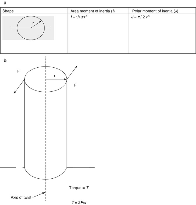

Fig. 3.1
(a) Moment of inertia and torque can be calculated using the shape of an object. (b) Torque is created by two forces acting in opposition around an axis of twist (Reprinted from Lucas et al. [3]. With permission from Springer)
When a rod is subjected to a torque or twisting, such as when a child with a growing rod turns his or her trunk in play activities and one end rotates relative to the other, a shear stress is induced on the cross-section of the rod. The shear stress varies from zero in the axis to a maximum at the outside surface of the rod. Rod breakage can occur because of shear stress alone or in combination with bending of the rod (Fig. 3.2).
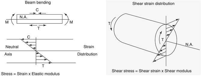

Fig. 3.2
Shear stress is the largest on the outside surface of a rod. Failure can occur because of shear stress or due to a combination of shear stress and rod bending
Each rod used to correct a deformity is able to withstand a certain amount of load as determined by the shape and composition of the rod. The load is the force that the deformed spine places on the rod as well as any additional forces from the child’s play activities. The structural rigidity determines the load capacity of the rod. It is a function of the material modulus and the rod geometry. Structural rigidity takes into consideration the loading mode: axial, bending, and torsion. Axial rigidity (EA) is the product of E × A. It reflects the ability of the device to resist axial loads in line with the longitudinal axis of the rod. Tensile or compressive axial loads are not usually a failure mode in growth modulation systems. Bending rigidity (EI), the product of E × I, reflects the ability of the device to resist bending moments applied perpendicular to the central axis of the rod. Most device failures occur when the bending rigidity of the device is too small to resist the applied bending moments. Torsional rigidity (GJ) is a product of G × J, and it reflects the ability of the device to resist torques around the axis of the rod. The more rigid a structure, the less it twists under a specific torque. Torsion may lead to device failure when a rod changes from a small radius to a larger radius in a non-gradual way (Fig. 3.3).
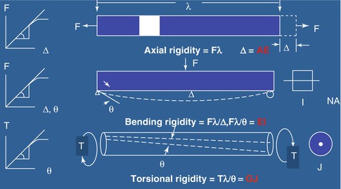

Fig. 3.3
Structural rigidity (modulus × geometric property). The more rigid a rod, the less it will twist. Failure of a rod may occur when there is a rapid transition between a small radius and a large radius
Failure can also occur at a stress concentration. A stress concentration is created when there is an abrupt change in structural geometry, such as cross-sectional diameter. It can also be induced by stress risers predisposing the device to failure. Localized stress concentrations may occur at holes, bends, and coupling sites (Figs. 3.4 and 3.5).
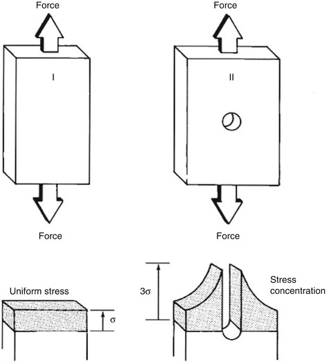
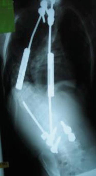

Fig. 3.4
Stress concentration. In the first image, uniform stress is applied across the entire block. In the second image, the center hole creates a stress concentration creating a much larger stress around the area of the hole

Fig. 3.5
Clinical example of a stress concentration. When a device changes abruptly from a smaller diameter to a larger diameter, a stress concentration is created. Here it is shown that the abrupt transition of the coupling point to the rod caused the device to fail. A rod of larger diameter may have minimized the potential for failure by reducing the stress concentration between the coupling and the rod
Fatigue failure, the most common mechanism of rod breakage, can occur in a material subject to a cyclic stress. Although the peak stress in each cycle is less than what is needed to make the material fail in a static test, constant repetition of load weakens the material and causes a sudden failure. It is like repetitively bending a coat hanger wire and eventually having it break. The fatigue life of a system depends on the fluctuation of stress, the mean stress level, and the way it varies over time. In an active child, small degrees of rod bending and torsion with normal activities can fracture a rod in time. Fatigue failure can be accelerated by stress concentrations, stress fluctuations, corrosion, and surface stress.
Another factor that can contribute to system failure is corrosion. Corrosion can occur because of a combination of both material and structural properties of the device. Corrosion is a result of the interaction between the metallurgical, mechanical, geometric, and electrochemical properties of the implant. When corrosion occurs, the material weakens. While the majority of materials used in growth modulation systems are Ti-based, the fabrication and finishing processes can vary widely. When two dissimilar metals are in contact, such as steel and titanium, an electrochemical reaction or galvanic corrosion can occur. A second type of corrosion, mechanically assisted crevice corrosion or fretting, happens as a result of relative motion of two metals. Modular junctions increase the potential for fretting. This happens across a mechanical joint, such as a screw and a rod, when intermittent load is applied. Corrosion can lead to the failure of the device because of material weakness, wear due to particles released from moving surfaces, and/or localized inflammation and osteolysis.
3.3 The Engineering Principles of the Spine and Its Remodeling Response to Deformity
The spine has six degrees of freedom (DOF). It can rotate axially, laterally, and sagittally and can translate (move) axially, laterally, and anteroposteriorly. A functional spinal unit (FSU) is made up of superior and inferior vertebrae and an intervertebral disc and has two DOF. Each FSU, with the exception of the cervical spine, is supported by ten ligaments. These ligaments protect the FSU by restricting motion and absorbing energy when loads are out of the normal range. The rib cage, attached to the spine through joints and ligaments, also increases the stability of the spine by restricting motion in all directions. Specifically, the costovertebral joint is critical in limiting motion during flexion and extension [4]. Using computer simulations, Andriacchi et al. [5] determined that the stiffness properties of the spine were greatly improved by the rib cage during flexion, extension, side-bending, and axial rotation [6].
The three-column concept of Denis assists in assessing the stability of the FSU when subjected to distraction, flexion, and extension forces and moments. Usually the neutral axis is located in the mid-dorsal region of the vertebral body. It bears much of the axial load and does not significantly distract or compress during flexion or extension.
When an applied constant load is placed on the spine over a period of time, there will be deformation. This is defined as creep. In scoliosis, a force is applied to correct the deformity. After the initial correction, a constant force remains on the spine. Over time, the progressive correction of the deformity that occurs is due to creep. When a constant load is applied, there is a continued progressive strain. Clinically, this occurs in the case of halo traction. When the initial applied load reduces over time, this is called stress relaxation. Clinically, this has implications for sequential or a series of incremental applied loads (Figs. 3.6 and 3.7). When constant deformation is applied, stress progressively decreases from initial load. Clinically, this occurs when spinal instrumentation loosens during scoliosis correction.
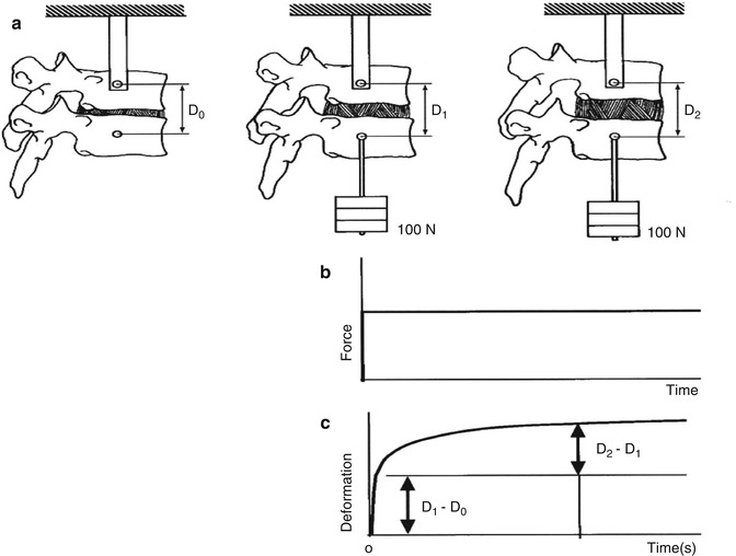
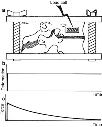

Fig. 3.6
(a) Creep is the deformation that occurs over time when there is a constant applied load, as in halo traction.(b, c) show that when a constant force is applied there is continued deformation over time

Fig. 3.7
When an applied load reduces over time, stress relaxation occurs
Creep reflects the viscoelastic nature of a material. While bone is weakly viscoelastic, soft tissue behaves partially like a solid and partially like a liquid and exhibits viscoelasticity. Viscoeleastic materials withstand higher loads to fracture and less elongation when stretched faster.
A compressive load is transferred between vertebral endplates through the intervertebral disc (IVD). Excessive compression will lead to degradation of the disc. The biomechanics of the disc change when subjected to bending or torsion. When bending loads are applied during flexion, extension, and lateral bending, the discs are subjected to both tension on the convex side and compression on the concave side. The torsional stiffness of the spine is mainly dictated by the orientation of the facets, which determines how much rotation can occur. Facets limit the degrees of freedom of motion. Facet design changes when comparing the thoracic spine to the lumbar spine. Thoracic facets are oriented in frontal plane and permit lateral bending and torsion. Lumbar facets are oriented in the sagittal plane and permit flexion and extension. The greatest change in orientation is seen at the thoracolumbar junction. Biomechanically, this creates a sudden change in stiffness creating a stress concentration. This is why the highest frequency of spine injury occurs here. Orientation of facets leads to coupled motion. Coupling occurs when two or more individual motions (i.e., lateral bending and rotation) occur simultaneously and cannot be produced individually. In scoliosis, there is twisting and warping as a consequence of this coupled motion. Surrounding muscles act as dynamic springs and dampen or attenuate deformation in response to applied load. At slow rates of loading, the vertebral body is more likely to fail. At higher rates of loading, muscles will be injured.
The surgeon must also take into consideration how the spine growth will be modulated by the applied mechanical loads. The Hueter Volkmann Law describes how loads affect the growth of bones. This was demonstrated in a study that showed how epiphyseal growth is affected by tensile and compressive forces [7]. Increased pressure or compression inhibits growth, whereas decreased pressure or tension accelerates growth. Using a rat tail model, Stokes et al. [8] showed that sustained compression of physiologic magnitudes inhibited growth by 40 % or more, while distraction increased growth by a much smaller amount.
In contrast, Wolff’s law states that bone remodels over time in response to mechanical loads. When the trabeculae are oriented along principal stress trajectory, bone is subjected to loads above or below what is normal and the bone responds. For example, increased intermittent stress stimulates bone formation where reduced intermittent stress causes bone resorption. For example, the ribs of attachment for the VEPTR tend to thicken with time, reflecting the reaction to stress of the rib cradle on the ribs. Adjacent muscles neutralize tensile loads and allow bone to carry increased compressive loads.
Correction obtained by growth modulation is dependent on growth remaining at each level. This dictates the number of FSUs and time of inhibition required to correct a deformity. Balasubramanian and Dimeglio estimated the growth per level per year, and this information can be used to mathematically predict the number of levels and years required to correct asymmetrical growth of the spine.
3.4 Specific Device Constructs and Their Response to Load Application Over Time
How the growth modulation system is fixed and loaded in vivo will have a large impact on the correction of the deformity and the longevity of the device. However, the patient’s anatomy, specifically the bone-anchor interface, limits the amount of distraction force that can be applied. Using a screw versus a hook at this interface will affect the amount of force that can be expended.
3.4.1 Bone Anchors
A pedicle screw is rigidly fixed in both cortical and cancellous bone. The outer diameter of the screw predicts pull-out strength, while the inner diameter determines fatigue strength. Screws function by converting the insertion torque into internal tension in the screw and into elastic reactions in the surrounding material [3]. In comparison, a hook is semi-constrained, allowing some motion or stress relief to occur at the bone-implant interface. Sublaminar wires are often used as a tension band across posterior spinal elements. As wire tension increases, it becomes a stiffer anchor point. For all anchors, the bone quality affects the stability of the bone anchor. Bone stiffness and strength vary with density squared. Using pedicle canal fill by using the widest screw possible maximizes the friction between the anchor and the bone, therefore minimizing the potential for failure.
Stay updated, free articles. Join our Telegram channel

Full access? Get Clinical Tree


