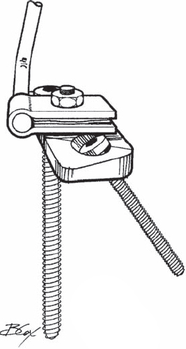
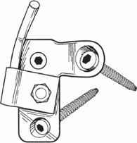
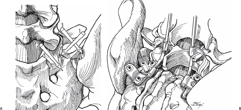
44 Jeff S. Silber The Chopin plate, also known as the Colorado II sacral plate, combines an S1 screw and a laterally placed sacral alar screw. It was introduced by Chopin in France and has been used in clinical practice since the early 1990s. The two-hole plate, or three-hole plate if pelvic fixation is also required, is placed on the dorsal aspect of the sacrum in a longitudinal direction (Fig. 44.1 ). The superior hole is for placement of an S1 pedicle screw angled medially (10 to 15 degrees) toward the sacral promontory, and the inferior hole is for placement of a sacral alar screw angled laterally (30 degrees). With the three-hole plate an additional hole located laterally can be utilized for fixation into the pelvis (Fig. 44.2 ). Located midway between the superior and inferior holes is a post that allows connection of the plate to the longitudinal component extending down from the lumbar spine. Fig. 44.1 Side view of the two-hole plate. Fig. 44.2 Axial view of the three-hole plate. Spinal pathology involving the lumbar-sacral junction may be due to trauma, infection, tumor, or congenital or degenerative disease. Commonly, fusion procedures need to include this junction to obtain stability and improve the overall biomechanics of the spine. Increased fusion rates have been reported with the use of instrumentation, and although posterior sacral pedicle screws are widely used, cases of fixation failure have been reported with their use. Screw failure is most commonly due to inadequate purchase, incorrect direction or depth of screw placement, and osteoporotic bone, especially in the setting of long fusion procedures that place high bending loads across this junction. Overall, based on biomechanical testing, S1 screws placed anteromedially into the sacral promontory with bicortical purchase tend to have the highest pullout and bending strength. Furthermore, the Chopin (Colorado II plate) may add additionally needed fixation points across the lumbosacral junction in various clinical scenarios. Biomechanical studies have demonstrated improved strength using this divergent two-screw construct compared with a single pedicle screw construct alone. This technique is especially useful in cases of highgrade (III–V) spondylolisthesis, long fusions to the sacrum, revision procedures, pseudarthrosis at the L5-S1 level, significant osteoporosis, sacral trauma, and scoliosis (neuromuscular) with pelvic obliquity requiring sacral and pelvic fixation. This technique should not be used if fusion to the pelvis and sacrum is not indicated or needed. The posterior-superior iliac spine may need to be removed or at least flattened with a rongeur or burr to make the plate seat flush against the pelvis. Unicortical versus bicortical screw placement is based on surgeon preference, as the increased pullout strength provided by the technique is due to the divergent placement of the two screws. If further pelvic fixation is needed, a three-hole plate utilizing a pelvic screw placed through the posterior-superior iliac spin may be utilized. Upon completion, intraoperative fluoroscopy or plain radiographs are obtained to confirm adequate screw placement and appropriate spinal alignment. In the prone position the lumbar spine and the sacrum are exposed inferior to the L5-S1 facet joints. The inferior articular process of the L5-S1 facet is removed to expose the superior facet of S1. Once exposed, the superior S1 articular facet is then removed to provide a flat surface for the Chopin plate. The plate is placed longitudinally along the flattened S1 superior articular process, with the top hole over the starting point of the S1 pedicle. The pedicle of S1 is cannulated, probed, and tapped prior to placement of the plate. The starting hole is about 4 to 5 mm lateral to the inferior aspect of the S1 superior articular process (Figs. 44.3 and 44.4). The S1 pedicle screw is not tightened all the way to allow rotation of the plate to the ideal location for placement of the alar screw. With the plate flat on the sacrum, an awl or burr is used to create a starting hole for the alar screw, which is cannulated with a pedicle finder followed by probing and taping. The screw is placed anterolaterally and parallel to the slope of the SI joint, being careful not to penetrate the joint that is located lateral to the screw placement (Figs. 44.3 and 44.5). Once the alar screw is placed and tightened, the S1 pedicle screw is tightened, bringing the plate flush to the dorsum of the sacrum. The screw is placed within the outer and inner cortices of the ileum (Figs. 44.3 and 44.6). Once the screws are placed, locking screws are then placed to prevent screw backout; they may be inserted in holes adjacent to the S1 and alar screws. Once the plate is placed, a connector is then attached to the post on the plate, which is then connected to either a 5.5-mm or 6.25-mm rod.
Sacral Plating Techniques (Chopin)
Description


Expectations
Indications
Contraindications
Special Considerations
Tips, Pearls, and Lessons Learned
Key Procedural Steps

Stay updated, free articles. Join our Telegram channel

Full access? Get Clinical Tree


