Authors
Number of patients
Mean initial elongation pre- to post-initial (cm)
Mean growth of instrumented area (cm) during treatment
Mean total length increase of the spine (cm)
T1–S1 increase (cm/year)
Space available for lung (SAL) ratio (pre/final)
Number of complications per patient
Moe et al. [18]
20
Not reported
2.9
Not reported
Not reported
Not reported
1.1
Luque et al. [20]
47
Not reported
2.6
Not reported
Not reported
Not reported
0.3
Klemme et al. [22]
67
Not reported
3.1
Not reported
Not reported
Not reported
0.81
Blakemore et al. [23]
29
Not reported
Not reported
Not reported
Not reported
Not reported
0.3
Akbarnia et al. [13]
23
5.0
4.67
9.64
1.21
0.87/1
0.57
Akbarnia et al. [26]
13
5
5.7
10.7
1.46
Not reported
0.46
38.3 Indications
Principles governing the treatment of EOS are adhered to when applying traditional growing rod techniques. There is a trend in recent years to employ a more aggressive treatment strategy. In idiopathic EOS curves, progression greater than 10°, major curve greater than 35°, and RVAD greater than 20° should prompt consideration for active treatment. When curve magnitude reaches 45° or more, consideration should be given for surgical intervention. Older patients with idiopathic EOS follow principles similar to those with adolescent idiopathic scoliosis. Documented curve progression and curve magnitude greater than 45° are indications for surgical intervention. However, curve angle alone should not be the main indication for surgical treatment. Deterioration of pulmonary function and other associated conditions leading to the impairment of quality of life may influence the decision to wait and accept some further progression or do an earlier intervention (Table 38.2).
Table 38.2
Indications for treatment
Indications for operative vs. nonoperative treatment in EOS | |
|---|---|
Nonoperative | Major curve <20°a |
RVAD <20°a | |
Phase 1 rib heada | |
Operative | Major curve >25°a |
RVAD <20°a | |
Phase 2 rib heada | |
Failure of brace/casting treatment | |
Documented progression of curve | |
Once the decision is made to treat the child surgically, the question should be asked as to which method would most consistently give good results with the least or most manageable complications for that particular child. The growing rod technique has the best indication in patients with idiopathic, neuromuscular, or syndromic scoliosis and absence of congenital anomalies. The dual growing rod has been found superior in clinical outcome to single-rod technique. A recent comparison of dual- vs. single-rod constructs by Thompson et al. [27] highlights this debate. The results quite convincingly favor the dual growing rod technique. Although the overall complication rate was slightly higher (19 %[3/16 patients] vs. 29 % [2/7 patients]), the amount of initial correction obtained and final correction sustained, as well as improved growth rate and T1–S1 length, make this a more effective treatment. The presence of a second rod allows some leeway for revision when one rod breaks or undergoes plastic deformation. In the single-rod construct, a broken rod or implant complication is urgent and cannot wait until the next scheduled lengthening (Table 38.3).
Table 38.3
Comparison of single and dual-rod techniques
Single rod | Dual rods | |
|---|---|---|
Unplanned trips to OR | Increased risk | – |
Implant-related complications | Increased risk | – |
Infection | No difference | No difference |
Growth (mm/year) | 6.8 | 11.3 |
Initial correction (major curve %) | 38 | 47 |
Maintenance of correction (%) | 14 | 40 |
Bess et al. [24] further highlighted these differences from the Growing Spine Study Group (GSSG) database review of 910 growing rod surgeries. They found that the need for reoperation was lower in the dual vs. single group for complications. Also, the rate of implant-related complications was higher in the single-rod group. Superficial wound problems were greater in the dual-rod group due to the bulkiness of implants, but did not lead to a need for additional surgeries. The construct of the dual rod is also biomechanically favorable with improved initial curve correction and maintenance of correction.
Although the dual growing rod system may be somewhat more prominent than single rods, it certainly is lower profile than the current available rib devices such as VEPTR. Furthermore, dual growing rods more specifically address the pathology it treats compared to VEPTR. When comparing this technique to VEPTR, the main distinction that should be made is in the very indication. If a patient has thoracic insufficiency syndrome (TIS) with multiple congenital anomalies and stiff thorax, then the VEPTR may provide a better treatment modality. However, in children with scoliosis without chest wall anomalies and TIS, it could be argued that the growing rod constructs is lower profile and more directly addresses the spinal deformity. With its anchor points on the cephalad and caudal ends of the spine, it avoids attachment to the ribs and therefore avoids associated pulmonary complications such as chest wall stiffness. As the goal of this technique is growth modulation, it can be argued that placing anchors on a mobile segment away from the spine (on ribs) will result in a lower transmission of force on the spine, and consequently there is less stimulation of growth. For this reason, when growth modulation is the goal, growing rods are the most reliable way to accomplish this. No information on T1–S1 length is available following VEPTR procedures to date (Tables 38.4 and 38.5).
Table 38.4
Indications for distraction-based devices
Indications | Contraindications | |
|---|---|---|
Chest wall distraction (VEPTRa) | Thoracic insufficiency syndrome b | Skeletal maturity |
Skeletally immatureb | Poor rib bone stock | |
Congenital scoliosis/fused ribs | Absence of proximal ribs | |
Chest wall deficiency | ||
Spine distraction (growing rods) | IEOS | Skeletal maturity |
Neuromuscular scoliosis | ||
Scoliosis associated with syndromes |
Table 38.5
Predictable complications of two distraction-based nonfusion techniques
Growing rod | Chest wall distraction |
|---|---|
Multiple surgeries, infection | Multiple surgeries, infection |
Rod breakage | Drift of device attachments, brachial plexus injury |
Spine stiffness or fusion | Chest wall stiffness |
Traditional growing rods have been used for the treatment of EOS with a variety of etiologies such as idiopathic, neuromuscular, congenital, and syndromic disorders.
The growing rod may not be an effective procedure when there is no further growth potential or in patients whose primary problem is chest wall abnormalities and/or TIS. One also has to be careful in the presence of kyphosis to take precautions to avoid complications due to kyphosis, as discussed later in this chapter.
38.4 Surgical Technique
38.4.1 Surgical Technique for Single Growing Rods
38.4.1.1 Intraoperative
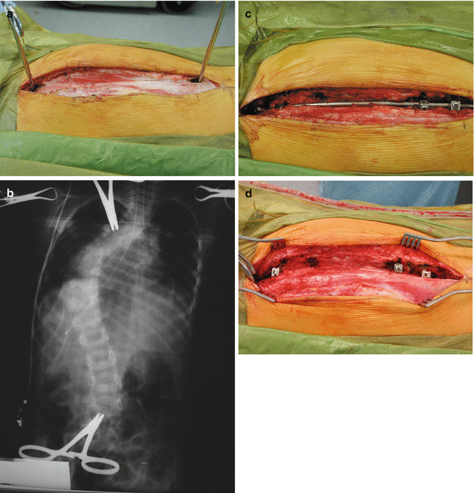
Our single growing rod construct consists of a proximal “claw” with hooks and a distal construct of either hooks or pedicle screws. The technique is similar to other spine procedures (Fig. 38.1a–d). After induction of general anesthesia, the patient is positioned prone on either the Hall-Relton four-poster frame or a Jackson table. Typically, a long, midline incision is made over that portion of the spine that is to be instrumented. The exact length is based on preoperative planning. The subcutaneous tissues are divided and the fascia exposed. One spinous process proximally and distally delineating the foundation sites is exposed and marked with a clamp. Intraoperative radiographs are obtained to identify the preplanned foundation sites. Once this has been accomplished, then the two or three adjacent vertebrae are exposed subperiosteally. The fascia between the foundation sites is also divided and the muscle thinned so that the rod will lie close to the spine. However, the laminae are not exposed or visualized. The distal foundation is usually constructed first. In the beginning, we used a claw construct with an over-the-top laminar hook proximally and a sublaminar hook distally. This allowed compression between the hooks. However, in the last 5 years, we have used a pedicle screw construct for the distal foundation. The proximal foundation consists of an over-the-top laminar hook proximally and a sublaminar hook in the next distal vertebrae. Occasionally, this may extend one additional level distally. This also allows for compression once the rod has been inserted. The size of the rod is based on the size of the patient. In most small children, a 5.5 mm rod is used, while in older children, a 6.35 mm rod is used. The interval between the foundations is measured with a silk suture and the rod measured. Typically, an additional 5 or 6 cm is added to this measurement to compensate for the initial distraction and to have enough extra length to allow it to be expanded at subsequent surgeries. The rod is appropriately contoured and inserted. When hooks are utilized for the distal foundation, they occasionally need to be open hooks to allow for the rod to be appropriately seated. Once the rod is inserted, it is grasped with rod holders and rotated to allow for a relatively normal sagittal plane alignment. The upper foundation is typically tightened first. The rod is distracted distally. This is always done under intraoperative neuromuscular monitoring. There is 4 or 5 cm of rod extending below the lower hook or screw. This is used for subsequent lengthenings. The wound is closed in layers. The fascia is closed over the entire construct. Typically, a drain is placed over the top of the fascia. The subcutaneous tissues and skin are closed in a standard manner. The latter is typically a subcuticular closure.


Fig. 38.1
(a) Intraoperative photograph demonstrating the incision and the exposure for the upper and lower foundations. The spinous processes at the planned levels are identified and marked. A radiograph is obtained to confirm the preplanned levels. (b) Intraoperative anteroposterior (AP) radiograph demonstrating identification of the foundation sites. (c) Hooks are typically used for the upper foundation and hooks and/or screws for the lower foundation. Hooks spanning two vertebral segments for the proximal and distal foundation were used in this patient. The muscle has been separated to allow the rod to lie as close to the bone as possible. However, the laminae, facets, and spinous processes are not exposed except at the foundation sites, which are fused. (d) Following rod insertion, a long segment of rod is left extending below the lower foundation. This is used to expand the rod and maintain spinal length. The fascia is closed over the instrumentation
38.4.2 Technique for Dual Rod
38.4.2.1 Initial Dual-Rod Procedure
Patient is brought to the operating room and general anesthesia is induced. Prophylactic antibiotics are administered. Patient is placed on the table in prone position over chest roles for small children and over a frame or Jackson table for larger patients. The entire back is prepped and draped in usual fashion.
The procedure includes preparation of cephalad and caudal foundations for anchor placement and performing a limited fusion, rod contouring, rod passage, and application of connectors. The index procedure can usually be performed through one or two midline incisions [26].
38.4.2.2 Technique of Preparing Foundations
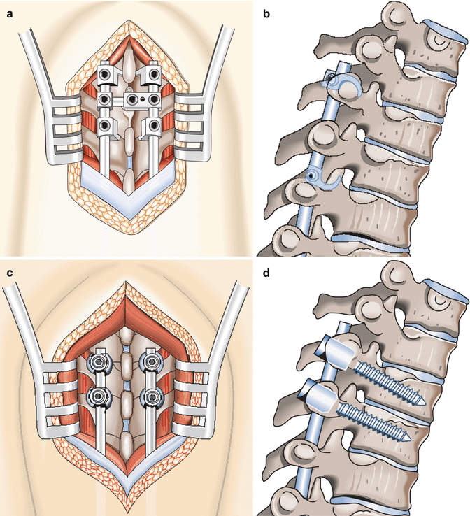
A foundation is defined as an assembly of at least two anchors and one or two rods that are stable and strong enough to accept corrective loads and to resist deforming loads without dislodgment of the anchors or plastic deformation of the rod [28]. In a typical dual-rod technique, we have used four anchors (hooks or screws) for each foundation for maximum stability (Fig. 38.2a–d). The exposures at the foundations are the only locations where the exposures are subperiosteal. Meticulous technique is employed to avoid a broad exposure and risking the occurrence of spontaneous fusion.


Fig. 38.2
Anteroposterior and lateral view of upper foundations using four hooks and a cross connector (a, b) or four screws (c, d)
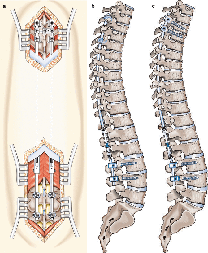
Selection of foundation sites is based on the type and location of the curve as well as the patient’s age and diagnosis. Patients with neuromuscular scoliosis, for example, may require longer instrumentation compared to those with idiopathic curves. The upper foundation anchors are generally placed at the T2–T4 levels in a claw fashion. If hooks are used at the upper foundation, the author’s preference is a supralaminar location for superior hooks. The inferior hooks are placed sublaminar under the lamina (facet), similar to the technique used with original Harrington hooks, in a “claw” construct (Fig. 38.3a, b). The superior hooks can be staggered over two or three levels to avoid crowding the spinal canal if this is a concern. Staggering hook levels, however, may interfere with the use of a transverse connector at the foundation level. In that case, the connector is attached just below the lower hooks. It is utmost crucial to achieve the best foundation stability at the initial surgery to reduce the possibility of failure, even at the expense of exposing three instead of two levels. A study by Mahar et al. [29] demonstrated the increased stability of a screw construct over hooks alone or hooks with cross-connectors showing the significance of adding a cross-link if all hook construct is used. We utilize both hooks and screws for foundations. It is our preference to use pedicle screws whenever possible; however, if anatomical considerations make this difficult, then hooks are another excellent option (Fig. 38.4a–c).


Fig. 38.3
Hook insertion maneuvers. Infralaminar hooks are inserted applying lateral to medial rotary motion (a); supralaminar hooks can be placed by medial to lateral rotation of hook holder (b)

Fig. 38.4
Considering patient’s age, anatomical provision and bone quality screws and hooks can be used as upper and lower anchors to provide strong foundations (a–c)
The caudal foundation is generally instrumented with four pedicle screws. The foundation levels are typically three levels below the lower end vertebra of the major curve. In the presence of pelvic obliquity, such as neuromuscular scoliosis, the distal foundation may be extended to the sacrum or ilium using intrailiac fixations. It is extremely important that the foundations be stable and as strong as the bone quality permits. Bone graft or bone graft substitutes are used to augment bony fusion across at the foundation sites including a facet fusion and secure foundation anchors.
38.4.2.3 Insertion of Dual Rods and Anchors
A low-profile pediatric implant system, with appropriate dimensions, such as 4.5 mm diameter stainless steel or titanium rods, is usually used. The rods are measured and cut into four segments, two for each side, and contoured for sagittal alignment. When tandem connectors are used, the rods should be cut in the region where the rod ends meet mostly at the thoracolumbar junction as this will be the best site for the tandem connectors. Appropriate contouring may help to correct the kyphosis using a cantilever maneuver when the deformity is flexible. One has to avoid extreme sagittal correction in one session to avoid anchor failure. The individual rods are passed subfascially as the tip of the rod is felt at all times through the skin until it appears at the site of the upper foundation. They will then be secured to their respective anchors and a cross-link can be added if necessary. Mahar et al. did not show any benefit of cross-connecting if four pedicle screws are used for fixation, but did find significantly more strength associated with a cross-link and hook foundation. The lower foundation is then prepared and contour rods are connected to the caudal anchors. The tandem connectors are then placed at the thoracolumbar junction by first sliding them cephalad and then caudal. The thoracolumbar region is chosen for tandem connectors, as this is an area of the spine that is anatomically straight. The tandem connectors are rigid and do not bend; therefore, this location has the least effect on sagittal alignment. Lengthenings are done mostly by loosening the screw of the upper rod; therefore, only a short segment of the lower rod should be attached to the tandem connector leaving room for more of the upper rods to be inside the connector. This segment of the rod should not be contoured to allow entry into the straight connector. The tandem connectors are placed in their least prominent position to achieve the lowest profile possible. If there are set screws with connectors, they can be placed facing either medially or laterally. Turning the tandem connectors medially (set screw heads facing medial) makes the reach easier for the screws and possibly allows minimally invasive access during lengthening procedures. The lateral placement however may have a lower profile. Another option for rod connection is side-to-side connection. When side-to-side connection is used, the location of the connectors may vary and the rods in those segments can remain contoured for appropriate sagittal alignment.
Stay updated, free articles. Join our Telegram channel

Full access? Get Clinical Tree


