(A) Illuminated skull demonstrating transducer position over the temporal bone for axial planes. (B) T2-weighted MRI, coronal image, demonstrating five axial insonation planes (1 = midbrain, 2 = thalamic, 3 = cella media, 4 = upper pons, 5 = lower pons). (C) Illuminated skull demonstrating transducer position over the transtemporal bone for anterior (yellow) and posterior coronal plane (orange). (D) Three-dimensional (3D) time-of-flight magnetic resonance angiography (TOF MRA), lateral maximum intensity projection (MIP) showing the insonation field and detectable vessels using the anterior (yellow) and posterior coronal plane (orange).
Examination should start in the midbrain plane as most vessel segments can be identified there, and the probe can be placed perpendicularly without relevant inclination. The midbrain appears as a butterfly-shaped hypoechogenic structure surrounded by the hyperechogenic basal cisterns (Figure 9B.2C). By lowering the insonation angle by approximately 10° the upper pontine plane is displayed, and by an additional 10° the lower pontine plane is insonated (Figure 9B.2A,B). Ultrasound landmarks are the sphenoid bone anteriorly, the petrosal bone posteriorly – forming together the middle temporal fossa – and the hypoechogenic cerebellum. Pointing the transducer 10° upwards from the midbrain plane, the thalamic plane is displayed with both hypoechogenic thalami embracing the third ventricle and the hyperechogenic pineal gland behind the third ventricle (Figure 9B.2D). By further increasing the insonation angle by 10–20°, the cella media plane is disclosed with an angular cut of the hypoechogenic lateral ventricles (Figure 9B.2E). Transtemporal coronal planes may be the primary choice for analyzing cranio-caudally orientated vessels and may help to study stenotic lesions more precisely. The anterior coronal plane in particular visualizes the distal intracranial ICA and allows a more precise differentiation between the terminal ICA and the origin of both the MCA and ACA. The posterior coronal plane can be used to analyze the distal BA and to distinguish the proximal PCA from the SCA (Figure 9B.1C,D).
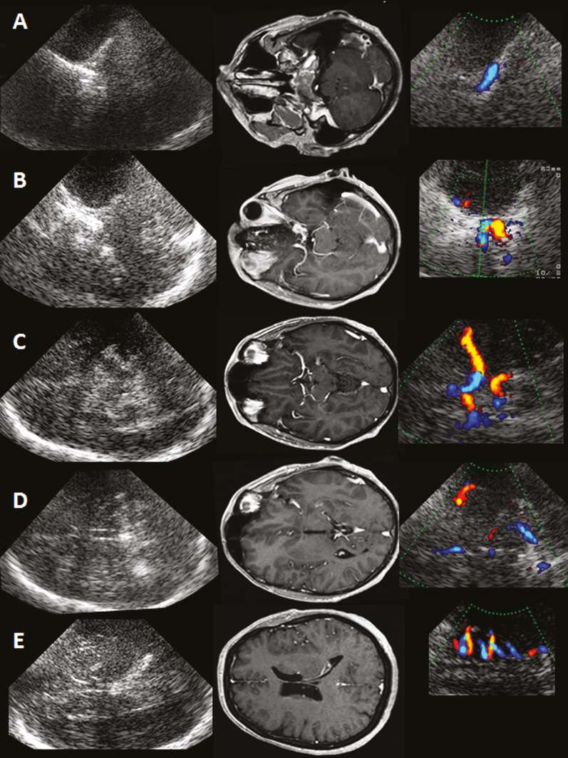
Five axial insonation planes. Left column: ultrasound B-mode images, transtemporal axial access. Middle column: corresponding MR contrast-enhanced MP-RAGE images rotated by 90° to correspond with ultrasound images. Right column: color-mode images demonstrating arterial vessel acquisition in different axial planes. (A) Lower pons plane: C6-ICA. (B) Upper pons plane: ICA-Siphon, OA, SCA, distal BA. (C) Midbrain plane: M1-MCA, M2-MCA, A1-ACA, P1-PCA, P2-PCA, cortical PCA branches, BA tip. (D) Thalamic plane: M2-MCA, M3-MCA, A2-ACA. (E) Cella media plane: M3-MCA.
The insonation planes allow a first orientation of intracranial vessel anatomy. The main goal, however, is an explicit identification of a certain vessel. Therefore, the transducer has to be adjusted according to the vessel of interest. Analyzing more distal parts of the main intracranial arteries or smaller arterial vessels with low blood flow velocities (BFVs) may require modifications of the settings, such as reducing the pulse repetition frequency (PRF) and the area of the color window, as well as increasing color gain. This may lead to “dirty” images with a profound color-aliasing phenomenon. Although this might impair the detection of circumscribed stenoses and the analysis of flow direction, it is recommended to use this strategy to obtain good spatial information of the insonated vessel segment as a “road map” and to prove the vessel integrity. Doppler spectrum analysis will then allow assessment of BFVs and flow direction in a second step. A triplex mode (simultaneous real-time assessment of B-mode, color-mode and Doppler-mode) if available is of special help in analyzing vessels passing through different insonation planes, which is true of almost all vessels in elderly patients. In subjects with limited bone window, ultrasound contrast agents consisting of stabilized microbubbles improve signal-to-noise ratio and help to overcome this problem [7,8]. Angle-corrected BFVs should only be used in the center of a vessel if at least 1.5 cm straight segment can be visualized [9]. As this is seldom the case because of the tortuous course of intracranial arteries, maximal achievable BFV should be measured without angle correction, and the depth of insonation should be documented to improve reproducibility of TCCS data.
Internal carotid artery: C6 segment
The intracranial part of the ICA can be divided into six segments [5]. The extracranial ICA enters the skull through the carotid foramen, where it follows an intrapetrosal course within the petrous carotid canal (petrosal segment). Its proximal part runs cranio-caudally, the distal part horizontally, the latter is referred to as C6. It leaves the base of the skull via the foramen lacerum vertically orientated along the side of the sphenoid bone (C5). From there it turns upward and forms the carotid siphon (C2–C4) within the cavernous sinus. It enters the subarachnoid space (C2) and rises to its terminal part (C1) where it bifurcates into the MCA and the ACA. Before this, it gives off several branches: at the C2/C3 level the OA, followed by the posterior communicating artery (PCoA) and the anterior choroid artery.
Provided that a sufficient bone window is present, all intracranial segments of the ICA can be insonated by TCCS in combined axial and coronal planes (Figure 9B.1A,B and Figure 9B.2A,B) [10]. In contrast to TCCS assessment of the terminal ICA as well as the carotid siphon, less attention has been paid to other segments, especially the C6 segment of the ICA despite its clinical relevance [10,11,12]. First, C6-ICA is an important site of atherosclerotic stenoses [13]. Second, its assessment also allows the evaluation of the hemodynamic consequences of high-grade proximal extracranial ICA stenoses if the distal extracranial ICA segment is not detectable and of suspected dissections near the skull base.
The C6 segment can be best visualized in axial lower pontine plane at the deepest point of the skull base with a flow direction away from the transducer (Figure 9B.1A) but also in the posterior coronal plane. In a study including 120 subjects with an excellent transtemporal bone window, the C6 segment was visible in up to 86% over a length of 14 ± 4 mm using an axial lower pontine plane. The straight vessel course and detectable vessel length allow the measurement of angle-corrected BFVs (66 ± 15 cm/s) and non-angle corrected BFVs (53 ± 14 cm/s) [10]. A missing C6 segment in spite of an excellent temporal acoustic bone window has to be related to the thickness of the osseous layer on the horizontal part of this vessel.
Ophthalmic artery: transtemporal insonation
The OA is the first branch of the ICA. It can be divided into an intracranial, intracanalicular and intraorbital segment. After arising from the supraclinoid part of the ICA the OA runs through the optic canal into the orbital socket, where it branches into segments that supply the eye and face. The main stem has a mean diameter of 0.7–1.6 mm. The OA may originate solely or partly from the middle meningeal artery in 1 to 2% of cases [14,15,16].
Insonation of the OA is usually performed transorbitally within the orbital socket using the 2-MHz transcranial transducer with a maximally reduced insonation power (mechanical index <0.26). A linear probe can be used (see Chapter 24). Alternatively, the proximal OA can be insonated transtemporally in the upper pons plane. When the carotid siphon is visualized the OA may be seen about 0–10 mm anteriorly to the carotid siphon and about 5 mm medially to the lesser wing of the sphenoid bone. Reducing the color box and the PRF a color-mode signal facilitates the visibility of the OA with a flow toward the transducer (Figure 9B.2A and Figure 9B.3). In a study including 105 subjects with patent transtemporal bone window the OA has been identified in approximately 90% of cases. Transtemporally measured systolic BFVs ranged from 15 to 58 cm/s and were comparable with transorbitally measured BFVs [17]. Vessel identification can also be confirmed by manual oscillation of the ocular bulb on the closed eye leading to a positive oscillation phenomenon in the Doppler spectrum of the OA.
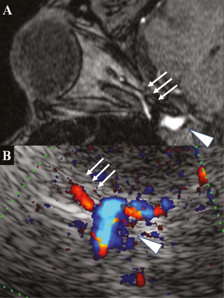
(A) 3D TOF MRA, axial source image, post-contrast image rotated 90° to correspond with the ultrasound image: note the contrast filling of the OA in the tip of the orbital socket (arrows) and the carotid siphon (arrowhead). (B) TCCS, transtemporal axial approach, upper pons plane, color-mode image with OA signal toward the transducer (arrows) emerging from the carotid siphon (arrowhead).
Middle cerebral artery: variations
The MCA can be divided into four segments [18]. TCCS usually enables good visualization of the M1 segment (see Chapter 9A). Provided that a good acoustic bone window is present, insular M2 segments as well parts of the opercular M3 segments can be seen in combined axial and coronal planes. Routinely, the axial midbrain insonation plane is used for the M1 segment. For evaluation of the division pattern of M1 and assessment of more distal M2 and M3 segments within the lateral fissure, the probe has often to be slightly turned upward toward the thalamic and cella media planes. The coronal insonation planes may be useful for vertically oriented opercular M3 vessels.
M1 branching pattern
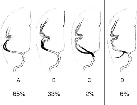
An M1 bifurcation or trifurcation can be assumed in TCCS if two or three M2 branches are visualized (Figure 9B.4). A division starting less than 10 mm distal to the MCA offspring is defined as medial bifurcation [18]. In the axial midbrain plane the medial bifurcation may be overlooked but will be recognized in the coronal anterior plane (Figure 9B.5). In a TCCS study of 50 subjects with excellent temporal acoustic windows, a regular bifurcation was seen in 65%, a trifurcation in 33% and a medial bifurcation composed of two roughly comparable branches in 2% [19]. TCCS prevalence of MCA bifurcation is higher compared with data from catheter angiography reporting a bifurcation in 48%. In anatomical studies even higher rates ranging from 66% to 88% were published [20,21,22]. Obviously TCCS and catheter angiography tend to misinterpret prominent early M2 branches with a trifurcation. Accordingly, the prevalence of a MCA trifurcation was lower in anatomical studies ranging from 12% to 26% [20,21,22].
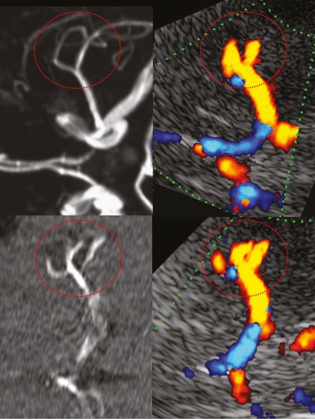
Anterior circulation mainly demonstrating MCA and ACA. M1 MCA division pattern in red circle. Left column: MRA, image rotated 90° to correspond with the ultrasound image. Right column: TCCS, transtemporal approach, axial midbrain plane, color-mode image showing M1 MCA division into a bifurcation (top) and into a trifurcation (bottom).
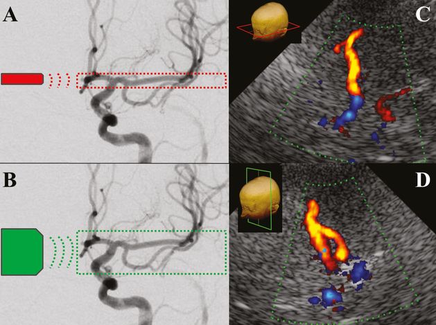
Left: digital subtraction angiography, anterior circulation. (A) Field in red circle indicating TCCS insonation area using an axial transtemporal approach. (B) Field in green circle indicating TCCS insonation area using an anterior coronal transtemporal approach. Right: TCCS, color images, medial MCA bifurcation. (C) In the axial midbrain plane the medial bifurcation is not visible. (D) The coronal anterior plane brings into light this anatomic peculiarity.
Early temporal M1 branch
The presence of an early temporal branch (ETB) emerging from the M1 main stem is of clinical importance. In distal M1 MCA occlusion, an ETB serves as collateral vessel presenting higher BFVs, which may be misinterpreted by TCCS as patent MCA main stem [23]. Angiographically ETB has been reported in 6% of cases [18], whereas in anatomical studies a small branch was present in almost all hemispheres [20]. In our own TCCS study, an ETB defined as a caudally emerging vessel signal in the proximal or middle M1 segment – best assessed in the anterior coronal insonation plane at an almost perpendicular angle – was seen in 26% of examined hemispheres (Figure 9B.6). In the axial midbrain plane, detection of the ETB was only possible after the recognition of this small vessel in the coronal plane. Systolic non-angle-corrected BFVs are low, usually about 40 cm/s. No side-to-side difference with regard to site prevalence or BFV was observed [19]. Figure 9B.7 summarizes the anatomical variants of M1 branching.
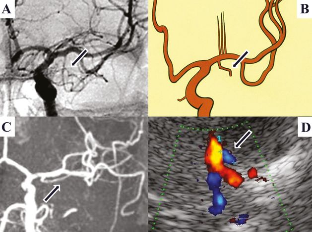
Early temporal M1-MCA branch (arrow). (A) Digital subtraction angiography. (B) Anatomical picture. (C) MRI, 3D TOF MRA, coronal MIP. (D) TCCS, transtemporal anterior coronal plane, color image: showing carotid T and a small blue-coded vessel segment merging from proximal M1 corresponding to an early temporal M1 branch.
Posterior cerebral artery: cortical branches
The PCA can be divided into four segments [24]. P1 represents its shortest and most proximal segment in the interpeduncular cistern with a length usually <10 mm from the tip of the BA to the PCoA. The P2 segment runs within the ambient cistern backward and initially slightly downward to the posterior margin of the midbrain. The long course of P2 is further subdivided into an anterior (proximal) and posterior (distal) part, each about 20 mm in length. The P2 usually gives off two main cortical branches, the anterior temporal artery (ATA) and the occipitotemporal artery (OTA). The P3 segment begins at the posterior margin of the midbrain and runs slightly upward and medially within the quadrigeminal cistern. It reaches the medial surface of the occipital lobe and often ends at the anterior limit of the calcarine fissure. At this point the P3 usually divides into two major branches defining the P4 segment, the calcarine artery (CA) following the calcarine fissure and the parietooccipital artery (POA) which follows the parietooccipital fissure [25,26,27,28].
TCCS allows differentiation between P1 and P2 segments according to real anatomy with the PCoA as border. Accordingly, almost all flow toward the transducer belongs to the proximal P2 and not to P1. Cortical PCA branches can also be elucidated as has been shown in a small TCCS study including 60 subjects with excellent temporal acoustic window [29]. Here, the ATA was visualized in the midbrain plane at the turning point between proximal and distal P2 (where flow direction changes from “toward” to “away” from the transducer) in 88% of cases. In the same plane, the more prominent OTA was detected in 96% of cases in the distal P2 segment. The POA, defined as a vessel in continuity with P3 between the thalamic and cella media plane, was detected in 69% of cases. Finally, the CA defined as a distal vessel near the midline in the midbrain plane was present in 62% of cases (Figure 9B.8) [29]. Compared to the P2 segment (63 cm/s) lower non-angle-corrected systolic BFVs were detected in cortical PCA branches with the highest values in the POA (44 cm/s) followed by the OTA and CA (both 36 cm/s) and ATA (25 cm/s). Following visual stimulation, the highest rise in diastolic BFV was observed in the CA, the main contributor to the striate and peristriate cortex (42%), followed by the POA (27%), the OTA (16%) and the ATA (9%). The P2 segment showed an increase of 30% [29].
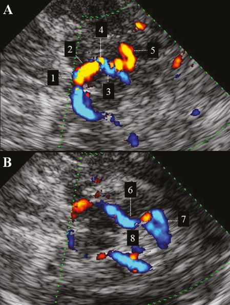
(A) TCCS, transtemporal insonation, upper pons to midbrain plane. Color-mode image of proximal PCA: 1 = P1-PCA; 2 = proximal (red-coded) P2-PCA; 3 = distal (blue-coded) P2-PCA; 4 = anterior temporal artery; 5 = occipitotemporal artery. (B) TCCS, transtemporal insonation, midbrain to thalamic plane. Color-mode image of distal PCA: 6 = P3-PCA; 7 = calcarine artery. 8 = parietooccipital artery.
Related posts:


Stay updated, free articles. Join our Telegram channel

Full access? Get Clinical Tree


