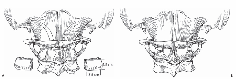
8 Norman B. Chutkan Review of fixation options for C1-C2 posterior fusion including posterior wiring, transarticular screws, lateral mass screws, and translaminar screws. The relevant anatomy and structures at risk are reviewed. Although posterior wiring is an accepted method of atlantoaxial fixation, newer techniques have been developed that provide rigid fixation. These include transarticular screw fixation, C1-C2 lateral mass screw fixation, and C2 translaminar screws. Although these techniques do allow for more rigid fixation, they are technically more demanding and are associated with an increased risk of complications. In cases of C1-C2 instability, there are several options for secure fixation of the atlantoaxial complex. The suitability of each technique depends on the specific anatomy and the presence or absence of intact posterior elements. Related to specific techniques, as follows. Detailed preoperative evaluation of the bone morphology and neurovascular anatomy is critical to maximize surgical success and minimize the risk of complications. Computed tomography (CT) and magnetic resonance imaging (MRI) facilitate determining the location of the vertebral arteries, assessing the reduction of the atlantoaxial complex, assessing the integrity of the posterior elements, and evaluating the pars of the axis. CT angiography provides better visualization of the vertebral arteries than does standard CT. Stereotactic image guidance systems may be beneficial in demonstrating the proposed screw trajectory. In cases where posterior wiring is being considered, care should be taken if there is significant anterior canal encroachment by hypertrophied bone (odontoid), pannus, infected tissue, or large tissue mass, as this may increase the risk of neurologic injury. For cases of posterior wiring, flexing the head on C1 can facilitate wire passage. Anatomic reduction should be achieved prior to passing wires. Large curved blunt needles can be used to pass sutures under the lamina. Wires or cables can then be pulled through. Unicortical grafts with a thick cancellous component should fit snugly against the decorticated posterior and inferior ring of C1 and the lamina of C2. In cases where screw fixation is being considered, it is important to remember that there is significant variation in bony morphology and vascular anatomy among individuals. Careful preoperative assessment facilitates determining the best options for screw fixation. The use of intraoperative tactile and visual landmarks as well as fluoroscopy is critical. Although not mandatory, stereotactic imaging may be of benefit. Direct palpation of the medial border of the C2 isthmus is most important, as it serves as a guide for correct medial-lateral screw placement. Increased thoracic kyphosis may present a challenge for percutaneous placement of transarticular screws. The venous plexus overlying the C1-C2 facet joint can lead to significant bleeding. This can be minimized with careful dissection and packing with hemostatic agents. Appropriate positioning prior to beginning the case is critical. The neck should be positioned with lower cervical flexion and midcervical protraction while maintaining reduction of the atlantoaxial complex. With posterior wiring, if wires or cables cannot be passed safely or easily under the lamina of C2, passing it through or around the spinous process should be considered. Exposure should be limited to the C1-C2 posterior elements. Care should be taken to avoid injury to the C2-C3 facet capsule. For posterior wiring, limit the exposure of C1 to 1.5 to 2 cm laterally from the midline to avoid injuring the vertebral artery. Free the edges of the lamina of C1 and C2. The interspinous ligament between C2 and C3 is maintained. A small, central soft tissue window is created between C2 and C3. A large blunt needle is used to pass a looped suture under C1 and C2. If a Gallie-type fusion is planned, a single suture is sufficient; however, a Gallie construct provides little rotational stability, and a Brooks-type construct is preferred. This requires the passage of two separate sutures. Wire or cables can then be pulled through. For a Gallie fusion a looped wire or cable is pulled under C1 and wrapped around the spinous process of C2. For a Brooks fusion two looped wires or cables are pulled under the lamina of C1 and C2. With a Gallie fusion a single large unicortical autograft is placed between the lamina of C1 and C2 and secured in place by tightening the wires or cables. In a Brooks fusion two corticocancellous autograft rectangular wedges are used (Fig. 8.1). The grafts should fit snugly once the wires or cables are tightened. Gaps between the graft and lamina can be filled with cancellous bone.
Posterior C1, C2 Fixation Options
Description
Key Principles
Expectations
Indications
Contraindications
Posterior Wiring
Transarticular Screws
C1-C2 Lateral Mass Screws
C2 Translaminar Screws
Special Considerations
Special Instructions, Position, and Anesthesia
Tips, Pearls, and Lessons Learned
Difficulties Encountered
Key Procedural Steps
Related posts:


Stay updated, free articles. Join our Telegram channel

Full access? Get Clinical Tree


